




Mobile Phone Shaft MIM Parts
Injection mold means that in the heating barrel of the injection machine, the plastic is heated and melted, pushed by the screw or Dussel, enters the mold cavity through the nozzle and the gating system of the mold, and the plastic is hardened and shaped in the cavity.
Product Introduction
Mobile phone shaft MIM Parts | |||||||||
Item | Material | Production Process | Sintering Temperature | Mold | Custom | ||||
Mobile phone shaft | 17-4 | Metal Injection Molding | 1550℃ | To be customized | Yes | ||||
Chemical Composition | C:≤0.07 | ||||||||
Available Materials | Low carbon stainless steel, titanium alloy (Ti, TC4), copper alloy, tungsten alloy, hard alloy, high temperature alloy (718, 713) | ||||||||
Finish | Dimensional Accuracy | Product Density | Appearance Treatment | Appropriate Weight | |||||
Roughness 1~5μm | (±0.1%~±0.5%) | 92~95% | Mirror Reflection | 0.03g~400g) | |||||
Mechanical properties | Tensile strength σb (MPa): aged at 480°C, ≥1310; aged at 550°C, ≥1060; aged at 580°C, ≥1000; aged at 620°C, ≥930 | ||||||||
Production Method
A method for manufacturing a metal powder injection molding mold for a mobile phone shaft

The utility model relates to the technical field of injection molds, in particular to a Mobile phone shaft MIM Parts.
Background technique
Injection mold means that in the heating barrel of the injection machine, the plastic is heated and melted, pushed by the screw or Dussel, enters the mold cavity through the nozzle and the gating system of the mold, and the plastic is hardened and shaped in the cavity. The injection mold is used for thermoplastics. The molding of products is used for the molding of thermosetting plastics.
Nowadays, the manufacturing of mobile phone parts on the market, such as the manufacture of mobile phone shafts, often uses metal powder injection molding. In the existing injection molding molds for mobile phone shafts, some molds are infused through a single injection hole, and then split injection. In this injection method, the fluidity of the alloy powder solution is poor, and the solidified material at the gate of the tapered flow channel of the injection mold is difficult to come out. When the molded object is taken out, there are convex edges on the surface of the object, which cannot meet the requirements of precision and quality. At the same time, most of the traditional forming molds do not have a clamping mechanism, and the connection between the upper cover plate and the lower cover plate of the mold is easy to produce gaps, which affects the molding quality of the object. For this reason, we propose an alloy powder injection molding for mobile phone shafts. mold to solve the above problems.
Technical Realization Elements
The purpose of this utility model is to provide a metal powder injection molding mold for mobile phone shafts, in order to solve the problem that the fluidity of the metal powder solution proposed in the above background technology is poor, and the solidified material at the gate of the tapered flow channel of the injection mold is difficult to come out , When taking out the molded object, there is a problem that there is a gap between the upper cover plate and the lower cover plate of the mold that leaves a convex edge on the surface of the object.
In order to achieve the above purpose, the utility model provides the following technical solutions: a metal powder injection molding mold for a mobile phone shaft, including a lower mold base, the corner of the lower mold base is fixedly connected with a limiting column, and the limiting column There is an upper formwork running through the top of the upper formwork, a groove is opened at the center of the lower mold base, and a style plate is placed inside the groove, grooves are set on the left and right sides of the top surface of the upper formwork, and the inside of the groove is installed There is an injection mechanism, the injection mechanism includes a sealing plate, the sealing plate is inserted into the groove on the surface of the upper template, the top end of the sealing plate is fixedly connected with a cover plate, and an injection tube runs through the center of the cover plate , the inner wall of the groove on the surface of the upper template is provided with a through hole, the surface of the lower mold base is provided with a guide tube, and the top of the guide tube communicates with the through hole of the groove on the upper template.
A mold locking mechanism is installed on the side of the lower mold base, and the mold locking mechanism includes a connecting frame, the inner wall of the connecting frame is hinged with a clamping shaft, and the surface of the clamping shaft is provided with external threads, and the clamping shaft passes through the external The threaded connection has a screw sleeve, and the surface of the upper template is fixedly connected with a limit block at the position corresponding to the connecting frame. The lower mold base and the upper template are closed through the rotation of the sleeve to avoid gaps in the connection between the lower mold base and the upper template. , to ensure the tight connection between the lower mold base and the upper template.
The surface of the clamping shaft is sleeved with a clamping block. The cross section of the clamping block is a pentagonal structure. Insert and snap on the surface of the limit block, so as to prevent the card shaft from shaking inside the limit block and affect the connection effect between the lower die base and the upper die plate.
The right side of the card shaft is fixedly connected with a spherical bump, and the outer diameter of the spherical bump is larger than the inner diameter of the central through hole of the swivel, and the spherical bump has a certain limit effect on the swivel to prevent the swivel from falling off easily .
The surface of the rotary sleeve is provided with arc-shaped grooves, and the arc-shaped grooves are distributed around the surface of the rotary sleeve. Through the arc-shaped grooves, the friction force between the staff's hand and the rotary sleeve is increased to prevent the rotary sleeve from rotating and sliding.
A trimming mechanism is installed at the central position of the upper template, and the trimming mechanism includes a connecting block, which is fixed on the surface of the upper template, and a threaded rod is installed in the central position of the connecting block, and the threaded The surface of the rod is threadedly connected with a sleeve frame, and the left and right sides of the bottom end of the sleeve frame are fixedly connected with connecting seats, and the bottom end of the connecting seat is fixedly connected with a cutter through bolts, and the cutter penetrates the surface of the upper template, and through the cutting The knife moves to trim the blank to avoid the generation of burrs and bumps.
The top of the threaded rod is fixedly connected with a handle, and the surface of the handle is provided with vertical grooves, and the vertical grooves are distributed around the surface of the handle, and the friction is increased through the vertical grooves to prevent the staff from rotating Slips when twisted.
The vertical section of the guide tube is an l-shaped structure, and the inner angle of the guide tube is an arc structure. Through the arc design of the inner angle of the guide tube, the flow fluency of the injection is improved to a certain extent.
Compared with the prior art, the beneficial effects of the utility model are:
(1) The device is equipped with a trimming mechanism. Compared with the traditional structure, when the object is metal injection molded, the sleeve frame moves on the surface of the threaded rod through the rotation of the threaded rod, and the cutter is driven to rotate through the connecting seat during the movement of the sleeve frame. , the cutter cuts the edge of the injection hole of the molded object while moving, so as to ensure the flatness of the edge of the molded object and improve the molding accuracy of the object. Improve the fluidity of the injection;
(2) The device is equipped with a mold locking mechanism. When the upper mold plate and the lower mold base are closed, the clamping shaft is rotated and inserted inside the limit block, and the rotary sleeve is rotated at the same time. During the movement, the rotary sleeve is clamped Squeeze the block, so that the clamping block is inserted into the groove of the limit block, so as to fix the lower mold base and the upper template, ensure the fastening effect of the connection between the lower mold base and the upper template, and avoid the connection between the lower mold base and the upper template Gaps are generated, which affect the molding quality of the object.
Description of drawings:
In order to more clearly illustrate the technical solutions in the embodiments of the present invention or the prior art, the following will briefly introduce the accompanying drawings that need to be used in the description of the embodiments or the prior art. Obviously, the accompanying drawings in the following description These are only some embodiments of the utility model, and those skilled in the art can also obtain other drawings based on these drawings without creative work.
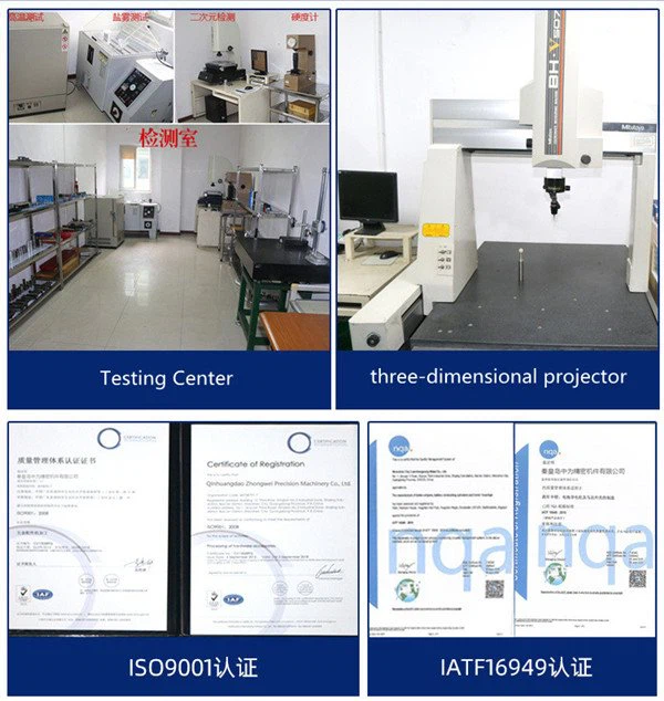
Detection Systems
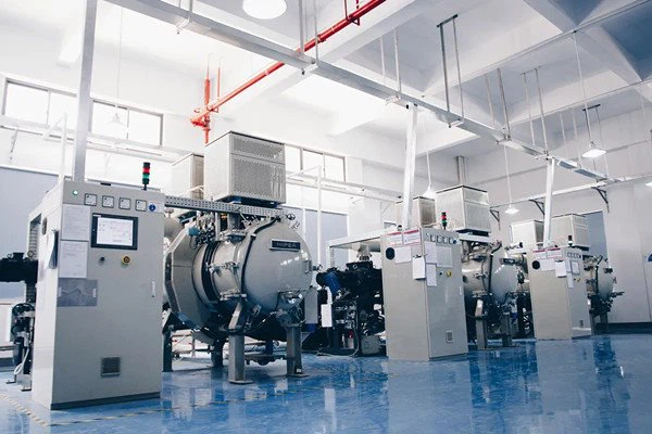
Metal Injection Molding Process





Send Inquiry
