
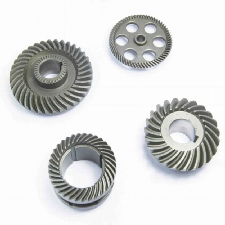


Large Bevel Tooth PM Sintered Part
Bevel gears are used for transmission between intersecting shafts. Traditional bevel gears are produced by casting models, and the processing is cumbersome and complicated. In the prior art, metallurgical technology is used to produce gears, and metal powder is processed into gears. Simple, but in the prior art, the gear and the gear shaft are all processed in one piece, which is difficult to process, high scrap rate, and high processing cost.
Product Introduction
|
Large bevel tooth PM sintered part |
||||||
|
Item |
Material |
Production Process |
Sintering Temperature |
Mold |
Custom |
|
|
Large bevel tooth powder metallurgy |
40rc |
Powder metallurgy |
1180℃ |
To be customized |
Yes |
|
|
Chemical composition |
C:0.37~0.44 Si:0.17~0.37 Mn:0.50~0.80 Cr:0.80~1.10 Ni:≤0.30 P:≤0.035 S:≤0.035 Cu:≤0.25 Mo:≤0.10 |
|||||
|
Available Materials |
Low carbon stainless steel, titanium alloy (Ti, TC4), copper alloy, tungsten alloy, hard alloy, high temperature alloy (718, 713) |
|||||
Product advantages
|
Smoothness |
Dimensional accuracy |
Product density |
Appearance treatment |
Appropriate weight |
|
Roughness 1~5μm |
(±0.1%~±0.5%) |
92~95% |
According to customer requirements |
0.03g~400g) |
|
mechanical properties |
Sample blank size (mm): 25 heat treatment: Heating temperature for the first quenching (℃): 850; coolant: oil Second quenching heating temperature (°C):- Tempering heating temperature (°C): 520; Tensile strength (σb/MPa): ≥810 (when the actual hardness is 25HRC) Yield point (σs/MPa): ≥785 Elongation after break (δ5/%): ≥9 Reduction of area (ψ/%): ≥45 Impact absorption energy (Aku2/J): ≥47 Brinell hardness (100/3000HBW) (annealed or high temperature tempered state): ≤207 |
|||
Process Flow

The utility model relates to the technical field of mechanical parts, in particular to a powder metallurgy bevel gear.
Background technique:
Bevel gears are used for transmission between intersecting shafts. Traditional bevel gears are produced by casting models, and the processing is cumbersome and complicated. In the prior art, metallurgical technology is used to produce gears, and metal powder is processed into gears. Simple, but in the prior art, the gear and the gear shaft are all processed in one piece, which is difficult to process, high scrap rate, and high processing cost.
Technical realization elements:
The technical problem to be solved by the utility model is: in order to overcome the disadvantages of integral processing of the gear and the gear shaft in the prior art and high scrap rate, the utility model provides a powder metallurgy bevel gear.
The technical scheme adopted by the utility model to solve its technical problems is: a powder metallurgy bevel gear, including a bevel gear part and a gear shaft part made of powder metallurgy split parts, and a bevel gear part and a gear shaft for connecting the parts are sequentially connected from left to right as an integral locking assembly, the right side of the bevel gear part is provided with a first limiting part connected with the gear shaft part, and the left side of the gear shaft part is provided with a The bevel gear part is connected to the second limiting part in a form-surface connection, and the first limiting part is connected to the second limiting part by inserting.
The bevel gear part is used for the transmission between the intersecting shafts, the gear shaft part is used to fix the position of the bevel gear part to ensure the stable operation of the bevel gear part, and the first limit part and the second limit part cooperate to replace the key and The fit of the keyway is fixed firmly, and the locking assembly is used to connect the bevel gear part and the gear shaft part sequentially from left to right as a whole. Powder metallurgy technology is used to process the gear separately, and the metal powder is processed into the bevel gear part and the gear shaft part, and the bevel gear part and the gear shaft part are assembled into one body by using the locking component, which is simple in processing, low in scrap rate, and saves energy. Processing costs.
Further, the first limiting portion is a groove with a polygonal cross-section, and the second limiting portion is a protrusion that cooperates with the groove. The cooperation of the protrusion and the groove of the polygonal structure replaces the cooperation of the key and the keyway in the prior art, which is convenient for processing, not easy to wear, and securely fixed.
Preferably, in order to facilitate the processing of the bevel gear part and the gear shaft part and securely fix the bevel gear part and the gear shaft part, the cross section of the first limiting part is a triangular structure, a quadrilateral structure or a hexagonal structure.
Further, the bevel gear part is further provided with a first limiting groove and a first through hole which communicate in sequence from left to right in the axial direction, and the first through hole communicates with the first limiting part.
Further, the gear shaft part also includes a connecting part, the second limiting part and the connecting part are sequentially connected from left to right, the gear shaft part is axially provided with a second through hole, and the connecting part A counterbore is provided on the right side, and the second through hole communicates with the counterbore.
Further, in order to facilitate the clamping mechanism to clamp the gear shaft part, the gear shaft part can still rotate in the axial direction, and the connecting part is a spherical structure.
Further, the locking assembly includes a screw and a nut, the head of the screw is set in the counterbore, the nut is set in the first limiting groove, and the screw passes through the first hole. The hole and the second through hole cooperate with the nut. The screw passes through the first through hole and the second through hole and cooperates with the nut to fixedly connect the bevel gear part and the gear shaft part, and the gears are assembled into one body. The operation is simple and the production cost is low.
Further, in order to prevent the nut from rotating with the screw when the screw is tightened, causing the bevel gear part and the gear shaft part to be unreliably fixed, the cross section of the first limiting groove is rectangular, and the outer wall of the nut fits into the first limiting groove. Insert the nut into the first limiting groove, and the nut will not rotate along the axis.
Further, a boss is provided on the left side of the bevel gear part along the circumference of the first limiting groove.
The beneficial effects of the utility model are: a powder metallurgy bevel gear provided by the utility model adopts powder metallurgy technology to process the gear separately, and the metal powder is processed into a bevel gear part and a gear shaft part. The bevel gear part and the gear shaft part are assembled into one body, the processing is simple, the scrap rate is low, and the processing cost is saved.
1. Bevel gear part, 2. Gear shaft part, 3. First limiting groove, 4. First through hole, 5. First limiting part, 6. Second limiting part, 7. Connecting part, 8. Second through hole, 9, countersunk hole, 10, screw, 11, nut, 12, boss.
Detailed ways
Now in conjunction with accompanying drawing, the utility model is described in detail. This figure is a simplified schematic diagram, only schematically illustrating the basic structure of the utility model, so it only shows the configuration related to the utility model.
As shown in Figure 1-10, a powder metallurgy bevel gear of the present invention includes a bevel gear part 1 and a gear shaft part 2 made of powder metallurgy split parts, and is used to connect the bevel gear part 1 and the gear The shaft part 2 is sequentially connected from left to right as an integrated locking assembly. The right side of the bevel gear part 1 is provided with a first stopper 5 connected to the gear shaft part 2. The gear shaft part 2 On the left side, there is a second limiting part 6 connected to the bevel gear part 1 , and the first limiting part 5 and the second limiting part 6 are plugged and connected.
The first limiting portion 5 is a groove with a square cross-section, and the second limiting portion 6 is a protrusion matching the groove.
The bevel gear part 1 is further provided with a first limiting groove 3 and a first through hole 4 which communicate in sequence from left to right in the axial direction, and the first through hole 4 communicates with the first limiting part 5 .
The gear shaft part 2 also includes a connecting part 7, the second limiting part 6 and the connecting part 7 are sequentially connected from left to right, and the gear shaft part 2 is axially provided with a second through hole 8, A counterbore 9 is provided on the right side of the connecting portion 7 , and the second through hole 8 communicates with the counterbore 9 .
The connecting portion 7 is a spherical structure.
The locking assembly includes a screw 10 and a nut 11, the head of the screw 10 is set in the counterbore 9, the nut 11 is set in the first limiting groove 3, and the screw 10 passes through The first through hole 4 and the second through hole 8 cooperate with the nut 11 .
The cross-section of the first limiting groove 3 is rectangular, and the outer wall of the nut 11 is matched with the first limiting groove 3 .
The left side of the bevel gear part 1 is provided with a boss 12 along the circumference of the first limiting groove 3 .
installation steps:
The bevel gear part 1 and the gear shaft part 2 manufactured by metal powder through metallurgy are arranged in sequence in the axial direction, and the second stop part 6 is set in the first stop part 5, and the screw head of the screw 10 is set on the countersunk head In the hole 9, a nut 11 is arranged in the first limiting groove 3, and the screw 10 passes through the first through hole 4 and the second through hole 8 to cooperate with the nut 11 to tighten the bevel gear part 1 and the gear shaft part 2 to form a whole.
Inspired by the above-mentioned ideal embodiment according to the present utility model, through the above-mentioned description content, relevant staff can make various changes and modifications without departing from the scope of the present utility model. The technical scope of this utility model is not limited to the contents in the description, and its technical scope must be determined according to the scope of the claims.
Metal Injection Molding Process

Detection Systems


Send Inquiry