


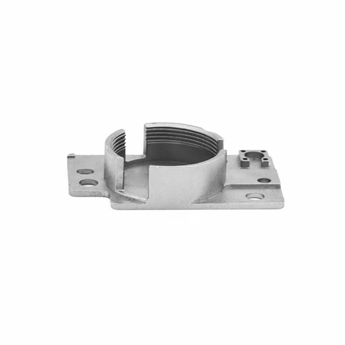


Optical Cavity MIM Parts
The metal injection molding process is a multidisciplinary technology and one of the advanced precision forming processes for metal parts.
Product Introduction
Optical Fiber Cavity MIM Parts | |||||||||
Item | Material | Production Process | Sintering Temperature | Mold | Custom | ||||
Optical Fiber Cavity | 316 | Metal Injection Molding | 1350°C-1500°C | To be customized | Yes | ||||
Chemical Composition | C:≤0.08 | ||||||||
Available Materials | Low carbon stainless steel, titanium alloy (Ti, TC4), copper alloy, tungsten alloy, hard alloy, high temperature alloy (718, 713) | ||||||||
Finish | Dimensional Accuracy | Product Density | Appearance Treatment | Appropriate Weight | |||||
Roughness 1~5μm | (±0.1%~±0.5%) | 92~95% | Mirror Reflection | 0.03g~400g) | |||||
Physical Properties | • 316 Annealed • 316L annealed • 316/316L spring tempered | ||||||||
Classification of metal injection molding process
The metal injection molding process is a multidisciplinary technology and one of the advanced precision forming processes for metal parts.
The metal injection molding process has gradually been recognized, accepted and valued by people. In order to meet the production needs of more complex parts, the latest technologies in many fields have been continuously introduced into the MIM industry, and vigorous innovations have been made, which also makes metal injection molding New technologies and new processes are constantly emerging and applied to development and production.
Below, we conduct an inventory.
1. Metal Microinjection Molding Technology (μ-MIM)
Micromechanics or microelectromechanical systems (MEMS) is a new interdisciplinary discipline developed in the late 1980s, and has been recognized as one of the key disciplines in the 21st century.
The practical application of micro-mechanical or micro-electro-mechanical systems depends on the progress of micro-processing technology. Metal micro-injection molding technology is the most effective method for mass production of high-precision, high-performance micro-metal or ceramic parts.
Metal microinjection molding technology refers to a process technology that uses the MIM process to produce micron-sized or micron-structured metal or ceramic parts, generally referring to precision parts with a size of less than 1mm or local micron-scale fine structures.
At present, with appropriate fine powder, metal or ceramic parts with a thickness of 25-50 μm, a local structure detail of less than 5 μm, and a surface roughness of 2-3 μm can be produced.
The size of metal injection molding parts develops to two extremes, and micron-sized precision parts have huge market capacity and development potential. The technological added value of these small parts is very high, such as optical fiber metal sleeves, laser catheters, printed circuit micro-drills, microelectronic actuators and dental medical parts, the price is 4,000 to 20,000 US dollars per kilogram.
Microinjection molding products have broad application prospects in actuators, sensors, pocket consumer products, weapons, aerospace, electronic assembly tools, oxygen analyzers, filters and medical care equipment.
The main obstacles limiting the development of micro-injection molding technology are the manufacture of precision micro-molds, the injection filling of narrow gaps and the handling of small parts.
The molds for producing such high-precision tiny parts are much more precise than conventional molds, and require the use of various advanced fine-processing technologies, such as photolithography, electroforming, micro-cutting, and micro-EDM. The above problems can be well solved by using processes such as LIGA (German plate-making, electroforming and injection molding three abbreviations) to manufacture plastic disappearing molds.
There are two ways to manufacture plastic lost molds by LIGA process:
One process is to use a mold to form a PMMA plastic mold core, insert the PMMA plastic mold core into the mold frame and directly perform metal injection molding, the PMMA plastic mold core and the MIM part blank will come out of the mold frame as a whole, and the MIM part blank will remain in the plastic mold core Direct degreasing and sintering become a one-step replication process.
Another process is to use the electroforming process to deposit a layer of metallic nickel on the surface of the PMMA plastic part, then peel off the PMMA plastic and the nickel shell, and then embed the nickel shell into the metal mold of the mold base process to form the MIM part blank. This becomes a two-step replication process.
The parts formed by the one-step copying process have higher precision, and solve the difficulties of demoulding and subsequent operations of the parts, but the cost is higher; the parts formed by the two-step copying process have lower precision and are suitable for mass production, but there are parts demoulding and subsequent operations are difficult.
2. Multi-component material composite injection molding technology
Parts made of a single chemical composition material are difficult to meet the various special requirements of the modern manufacturing industry for the complex integration of parts functions. Different parts of a part are made of different materials to meet different functional requirements. It is a development trend of modern parts manufacturing.

Schematic diagram of multi-component compound injection equipment
1. Tie rod; 2. Moving platen; 3. First forming mold; 4. Fixed platen; 5. First injection device; 6. Second injection device; 7. Second forming mold; 8. Mold rotation plate; 9. Clamping mechanism
The two-color (multi-color) injection molding technology widely used in the plastics industry is introduced into the field of metal injection molding, making it possible to mass-produce and efficiently treat complex metal or ceramic composite materials.
The principle of compound injection molding technology is that one injection machine is equipped with two or more sets of barrels at the same time, and the injection materials in each set of barrels are the same. The fixed mold of the multi-cavity mold can rotate around the rotating shaft, and different injection materials are injected into different cavities at each position. The initial injection blank is left in the innermost part, and the mold is opened after cooling, but it is not demoulded immediately. After the fixed mold is rotated to a certain angle, the fixed mold is closed, and the entire cavity expands outward relative to the first injection blank, and then the second injection molding of different injection materials is performed. Each part is made by multiple injections, and finally ejected from the mold.
The introduction of multi-component material composite injection molding technology can meet the requirements of single part functions, performance integration and compounding, saving precious raw materials, and reducing costs.
Composite technology has broad application prospects in many fields, such as steel-tungsten carbide or ceramic cutting tools, precipitation hardened stainless steel-iron-aluminum alloy fuel injectors, magnetic and non-magnetic electronic components, etc. have been successfully applied.
Regarding the first and second articles, please refer to read a more detailed introduction: [Technology] Metal Injection Molding New Technology: Introduction to μ-MIM and 2C-MIM Process
3. Gas (liquid) body-assisted molding technology
The working principle of gas (liquid) body-assisted molding is to inject a certain amount (volume fraction of 50%~80%) of molten injection material into the mold cavity, and then fill the pressurized gas or water from the inside of the melt to make the product form a hollow. The molten injection material expands and fully adheres to the inner wall of the mold cavity. Since the core of the thicker part of the product solidifies last, this part is most likely to form a hollow.

Since the volume change with pressure is much smaller than that of a gas, the flow of water and the wall thickness forming the hollow are more easily controlled. The gas (liquid) body-assisted molding process increases the degree of freedom in design, and the products with large wall thickness differences are easy to form; the injection pressure can be reduced, and the internal pressure distribution of the product is more uniform; the stress of the product is reduced, and the warping deformation is reduced. The collapse is reduced and the surface quality is improved; it can shorten the degreasing time, reduce material consumption and reduce the weight of parts.
Gas (liquid) body-assisted molding technology has been successfully applied to golf heads, door handles, handicrafts and other fields with remarkable results.
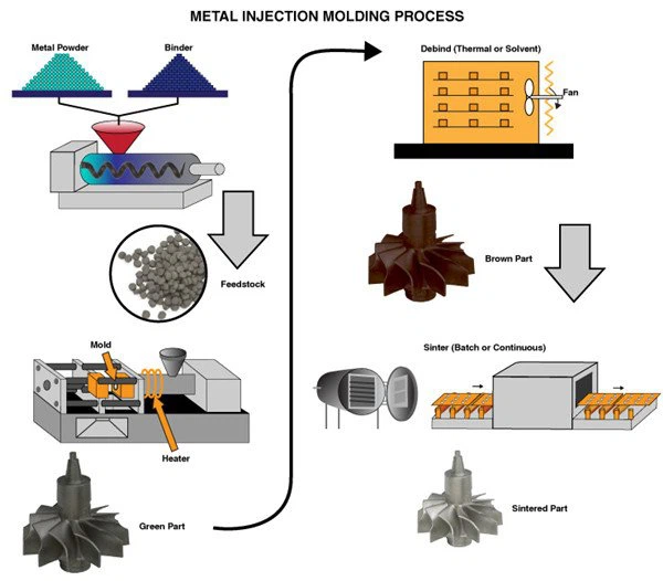
Metal Injection Molding Process
Detection Systems


Send Inquiry
