


Electronic Lock Cylinder MIM Parts
At present, the molding of lock cylinder accessories usually adopts the method of powder injection, that is, the mixture of metal powder and organic binder is injected into the cavity of the forming mold. According to this method, a metal sintered body close to the final shape can be manufactured.
Product Introduction
Electronic lock cylinder MIM Parts | |||||||||
Item | Material | Production Process | Sintering Temperature | Mold | Custom | ||||
Electronic lock cylinder | 304 | Metal Injection Molding | 1350°C-1500°C | To be customized | Yes | ||||
Chemical Composition | C:≤0.08,Si :≤1.0 Mn :≤2.0, Cr :18.0~20.0,Ni :8.0~10.5, S :≤0.03,P :≤0.035 N≤0.1 | ||||||||
Available Materials | Low carbon stainless steel, titanium alloy (Ti, TC4), copper alloy, tungsten alloy, hard alloy, high temperature alloy (718, 713) | ||||||||
Finish | Dimensional Accuracy | Product Density | Appearance Treatment | Appropriate Weight | |||||
Roughness 1~5μm | (±0.1%~±0.5%) | 92~95% | Mirror Reflection | 0.03g~400g) | |||||
Mechanical behavior | Tensile strength σb (MPa)≥515-1035 | ||||||||
Metal Powder Injection Molding MIM Material Table
Material | Performance | After sintering | After heat treatment | Chemical composition of MIM products after sintering | |||||
304L | Density | ≥7.80 g/cm3 | C% | Ni% | Cr% | Mn% | Si% | Fe% | |
Tensile Strength | ≥500 MPa | ≤0.03 | 9-11 | 19-20 | ≤2.0 | ≤1.0 | Margin bal | ||
Hardness | ≥120 HV10 | ||||||||
Elongation | ≥50% | ||||||||
Yield Strength | ≥180 MPa | ||||||||
Metal Powder Injection Molding MIM Dimensional Accuracy Table
Size | General MIM Enterprise Manufacturing Tolerances | Generally | Special case |
1-4mm | +/-0.05 | +/-0.05 | +/-0.03 |
4-10mm | +/-0.10 | +/-0.07 | +/-0.05 |
10-20mm | +/-0.15 | +/-0.10 | +/-0.08 |
20-30mm | +/-0.25 | +/-0.15 | +/-0.10 |
Feature | General range |
| Special range |
Part size | 0.2-50g |
| 0.09-200g |
Wall thickness | 0.5mm or more |
| 0.25 or more |
Note: Special tolerance requirements can be achieved through secondary processing, such as: shaping, CNC.
Our Copmany
A high-tech enterprise specializing in R&D, production and service of metal powder injection molding (MIM) and ceramic powder injection molding (CIM). The company has a production workshop of more than 6,800 square meters and a production team of more than 230 people. It has a complete production system of design-mold.
Opening-batching-sintering-machining-grinding-polishing-assembly.
The company passed the ISO9001:2008 quality system certification in 2001, and obtained the high-tech enterprise certificate of Qinhuangdao City in 2005. Our company can produce various structural parts, functional parts and appearance parts with complex three-dimensional shapes according to the needs of different customers. Products are widely used in 3Chh, lock industry, watch and jewelry industry, medical equipment industry, household appliance industry, automobile industry, communication product industry, etc. Based on the talent team graduated from the Department of Powder Materials, the rigorous and standardized control process is the basis for each Industry customers provide quality products.
The utility model relates to the technical field of moulds, in particular to a mold suitable for powder injection molding lock cylinder accessories.
Background technique
At present, the molding of lock cylinder accessories usually adopts the method of powder injection, that is, the mixture of metal powder and organic binder is injected into the cavity of the forming mold. According to this method, a metal sintered body close to the final shape can be manufactured. Therefore, the secondary processing can be omitted or the amount of processing can be reduced, and the simplification of the manufacturing process and the reduction of the manufacturing cost can be realized.
However, the existing molds for lock cylinder accessories require manpower to mix the metal powder and the organic binder, and then pour it into the mold, which is not only time-consuming and laborious, but also the mixing degree of the artificially produced kneading material is relatively poor, which greatly The influence of its forming efficiency.
Aiming at the above problems, the utility model proposes a mold suitable for powder injection molding lock cylinder fittings.
Technical Realization Elements
●The purpose of this utility model is to provide a mold suitable for powder injection molding lock cylinder accessories, one end of the motor is connected with a stirring shaft, the outer surface of the stirring shaft is provided with multiple sets of stirring blades, and the lower end of the mixing box is provided with a discharge port. The bottom plate of the mixing box is inclined at an angle of at least 10 degrees to the discharge port, which is used to assist the mixture to slide to the discharge port. The upper end of the connecting block is movably connected with a movable mold, and is fixedly connected with a static mold. One side of the static mold is provided with a For sliding doors, pulleys are installed on the lower end of the movable mold, and the pulleys match the slideway components. There are two sets of slideway components, and the two sets of slideway components are symmetrically distributed about the center of the upper end of the connecting block. The side ends of the slideway components There is a groove, the inner wall of the groove is fixedly connected with an elastic layer, and the outer side of the elastic layer is fixedly connected with a rubber plate that is movably connected to the inner wall of the groove. The center of the inner wall of the slideway component is distributed symmetrically, thus solving the problems in the background technology.
● In order to achieve the above purpose, the utility model provides the following technical solutions: a mold suitable for powder injection molding lock cylinder accessories, including the outer mold body and the feed inlet opened on the top plate of the outer mold body, and the inner wall of the feed inlet movably connected For the mold cover, one side of the outer mold body is provided with multiple sets of storage drawers, one end of the storage drawer is provided with a forming unit, and the lower end of the feeding port is also provided with a stirring unit, and the stirring unit includes a A mixing box, and a motor installed on one side of the mixing box, one end of the motor is connected to a stirring shaft, the outer surface of the stirring shaft is provided with multiple sets of stirring blades, and the lower end of the mixing box is provided with a discharge port.
● Preferably, the bottom plate of the mixing box is inclined at an angle of at least 1 degree toward the discharge port, so as to assist the mixture to slide to the discharge port.
● Preferably, the forming unit includes a connecting block installed on the inner wall of the outer mold, and slideway components provided on both sides of the upper end of the connecting block. There is a sliding door on one side.
● Preferably, a pulley is installed at the lower end of the moving mold, and the pulley matches the slideway assembly.
● Preferably, two sets of slideway assemblies are provided, and the two sets of slideway assemblies are distributed symmetrically about the center of the upper end of the connecting block.
● Preferably, a groove is provided at the side end of the slideway assembly, an elastic layer is fixedly connected to the inner wall of the groove, and a rubber plate movably connected to the inner wall of the groove is fixedly connected to the outer side of the elastic layer.
● Preferably, there are two groups of grooves, elastic layers and rubber plates, and they are distributed symmetrically about the center of the inner wall of the slideway assembly.
● Compared with the prior art, the beneficial effects of the utility model are as follows:
● The utility model proposes a mold suitable for powder injection molding lock core accessories. When working, the staff put metal powder and organic binder into the mixing box through the feeding port, start the motor, and the motor drives the stirring shaft. Make the stirring blade fully stir it, the stirred mixture slides through the bottom plate of the mixing box to the discharge port, and falls into the forming unit from the discharge port, without manual mixing, saving time and effort, and the mixing effect is good, ensuring the forming efficiency.
● The utility model proposes a mold suitable for powder injection molding lock core accessories. The side end of the slideway assembly is provided with a groove, the inner wall of the groove is fixedly connected with an elastic layer, and the outer side of the elastic layer is fixedly connected with a movable connection in the groove. There are two groups of rubber plates on the inner wall of the groove, elastic layer and rubber plate, and they are all symmetrically distributed about the center of the inner wall of the slideway assembly. The elastic layer reacts to the rubber plate through its own elasticity, so that the rubber plate is clamped Pulleys, so as to enhance the stability of the movable mold when moving on the upper end of the slideway assembly through the pulleys, and ensure the forming quality.
● Detailed ways
The technical solutions in the embodiments of the present invention will be clearly and completely described below in conjunction with the accompanying drawings in the embodiments of the present invention. Obviously, the described embodiments are only part of the embodiments of the present invention, not all of them. example. Based on the embodiments of the present utility model, all other embodiments obtained by persons of ordinary skill in the art without making creative efforts belong to the scope of protection of the present utility model.
25. It should be noted that in this article, relational terms such as first and second, etc. are only used to distinguish one entity or operation from another entity or operation, and do not necessarily require or imply that these entities or operations There is no such actual relationship or order between the operations. Furthermore, the term "comprises", "comprises" or any other variation thereof is intended to cover a non-exclusive inclusion such that a process, method, article or apparatus comprising a set of elements includes not only those elements, but also includes elements not expressly listed. other elements of or also include elements inherent in such a process, method, article, or device.
26. Although the embodiments of the present invention have been shown and described, those skilled in the art can understand that various changes can be made to these embodiments without departing from the principle and spirit of the present invention , modification, replacement and variation, the scope of the present utility model is defined by the appended claims and their equivalents.
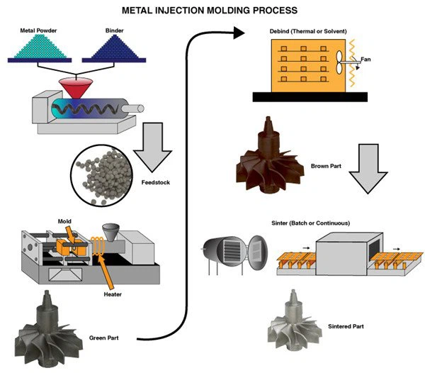
Metal Injection Molding Process
Detection Systems
1. Quality control: The defective rate is less than 0.1%.
2. Samples and trial runs will be 100% inspected during production and before shipment, sample inspection for mass production according to ISDO standards or customer requirements.
3. Testing equipment: flaw detection, spectrum analyzer, golden image analyzer, three-coordinate measuring machine, hardness testing equipment, tensile testing machine.


Send Inquiry