



Automotive Rocker MIM Parts
The rocker arm in a car is actually a double-arm lever used to redirect the force from the push rod to act on the end of the valve rod to push the valve open. The ratio of the arm lengths on both sides of the rocker arm is called the rocker arm ratio, and the rocker arm ratio is about 1.2~1.8, and one end of the long arm is used to push the valve.
Product Introduction
Automotive Rocker MIM Parts | |||||||||||
Item | Material | Production Process | Sintering Temperature | Mold | Custom | ||||||
Automotive Rocker | 316L | Metal Injection Molding | 1350°C-1500°C | To be customized | Yes | ||||||
Chemical Composition | C :≤0.08 | ||||||||||
Available Materials | Low carbon stainless steel, titanium alloy (Ti, TC4), copper alloy, tungsten alloy, hard alloy, high temperature alloy (718, 713) | ||||||||||
Finish | Dimensional Accuracy | Product Density | Appearance Treatment | Appropriate Weight | |||||||
Roughness 1~5μm | (±0.1%~±0.5%) | 92~95% | Mirror Reflection | 0.03g~400g) | |||||||
Mechanical properties | Tensile strength σb (MPa): ≥480 | ||||||||||
Thermal conductivity (W/(m*K)) | 100℃ | 300℃ | 500℃ | ||||||||
15.1 | 18.4 | 20.9 | |||||||||
Heat treatment | Olid solution 1010 ~ 1150 ℃ rapid cooling. | ||||||||||
The rocker arm in a car is actually a double-arm lever used to redirect the force from the push rod to act on the end of the valve rod to push the valve open. The ratio of the arm lengths on both sides of the rocker arm is called the rocker arm ratio, and the rocker arm ratio is about 1.2~1.8, and one end of the long arm is used to push the valve. The working surface of the rocker arm head is generally made into a cylinder, which can roll and slide along the end face of the valve stem when the rocker arm swings, so that the force between the two can act along the valve axis as much as possible. Lubricating oil channels and oil holes are also drilled in the rocker arm. In the threaded hole at the short arm end of the rocker arm, an adjustment screw for adjusting the valve clearance is screwed in, and the head ball of the screw is in contact with the concave ball seat at the top of the push rod.
The rocker arm is sleeved on the rocker arm shaft through the rocker arm bushing, and the latter is supported on the rocker arm shaft seat, and oil holes are drilled on the rocker arm.
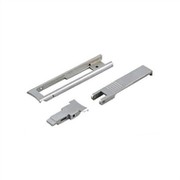
Automotive Rocker MIM Parts redirect the force from the push rod to open the valve.

Working principle of car rocker arm

One end is raised or lowered by the action of the rotating lobes of the camshaft (either directly or via a gear follower (lifter) and a pushrod), while the other end acts on the valve stem. When the lobes of the camshaft raise the outer lever arm, internally generated forces press against the valve stem, opening the acting valve. When the outer arm is allowed to return due to the action of the camshaft, the inner arm rises allowing the valve springs to compress closing the acting valve.
The drive cam works through the drive of the camshaft. It pushes the rocker arm up and down around the trunnion axis or the rocker axis. This reduces wear on the drive cam at the point of contact with the valve stem by the action of the cam's roller follower. Simultaneously a similar movement is transmitted to the second rocker arm through the action of another cam roller follower. This rotates the rocker shaft and transmits the action to the poppet valve through the gear follower. In this case, the intake valve is opened, allowing the gas to rush to the cylinder head.
The effective use of the lever arm (and thus the force that can be used on the valve stem) depends on the ratio of the rocker arm, which is the distance from the center of the rotating rocker arm to the tip to the distance from the center of rotation to the force acting on the camshaft or The ratio of distances at one point on the putter. Most current cars are designed with a rocker arm ratio closer to 1.5:1 to 1.8:1. However, in the past, there have been very few positive ratios (meaning the valve lift is greater than the cam lift), and even, previously used negative ratios (meaning the valve lift is less than the cam lift). Many pre-WWII engines used 1:1 (monoscopic) rocker arms.
Advantages and disadvantages of car rocker arm
Automotive Rocker MIM Parts The rocker arm type and the direct pressure valve drive design have their own advantages and disadvantages. In terms of power transmission efficiency, the direct pressure type is more direct and accurate than the rocker type; in terms of maintenance, the rocker type is less Much easier.
Because the gap between the direct pressure cam and the sleeve on the valve is adjusted by shims of different thicknesses, it is not easy to readjust when the engine is used for a certain number of hours and the valve gap increases; The valve clearance of the arm type is usually adjusted with a bolt, which can be done with a wrench. However, the shim material of the direct pressure valve has a certain degree of wear resistance, and the probability of wear is very low.
The development history of automobile rocker arm
Jonathan "Rung" Bacon arrived at these conclusions practically in the 19th century. In order to prevent other parts from being pressed on the valve stem, the rocker arm has two types: with stepped roller end and without stepped roller end, and the bearing arrangement at the fulcrum is made of light-weight, high-strength alloy material. Applications that improve their performance in this way strive to make the speed limit higher and higher. These superior technologies have led to the production of higher-end cars. Even the design of the geometry of the rocker arm is better studied, so that there is a broader explanation of how the cam forces the rocker arm to act on the valve. What is said above is the basis of Miller's US patent. Patent #4,365,785 issued to James Miller on December 28, 1982. Often referred to as the MID-LIFT patent, the previous design of the specific pivot point and rocker arm was based on the previous increased wear on the valve stem tip, and the inefficient arcing motion when the arcing motion passed through the rocker arm The forces transmitted to the valves, valve guides and other valve components as well as the active cam lobe will be reduced. Jim Miller's MID-LIFT patent set new and standard values for rocker arm geometry. It enables precise and reproducible angles of each engine's specific pushrod-to-valve strike. In order for the rocker arms to be perpendicular to each other, a rocker arm pivot point is designed. That is to say, as the push rod acts on the valve, the valve moves in the middle at the middle lift point.
Metal Injection Molding Process

Detection Systems




Send Inquiry
