


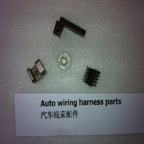
Automotive Wiring Harness MIM Parts
The automobile wiring harness is the main body of the automobile circuit network, and there is no automobile circuit without the wiring harness. With the improvement of people's requirements for the safety, comfort, economy and emission of automobiles
Product Introduction
Automotive Wiring Harness MIM Parts | |||||||||||
Item | Material | Production Process | Sintering Temperature | Mold | Custom | ||||||
Automotive Wiring Harness | 316L | Metal Injection Molding | 1350°C-1500°C | To be customized | Yes | ||||||
Chemical Composition | C :≤0.08 | ||||||||||
Available Materials | Low carbon stainless steel, titanium alloy (Ti, TC4), copper alloy, tungsten alloy, hard alloy, high temperature alloy (718, 713) | ||||||||||
Finish | Dimensional Accuracy | Product Density | Appearance Treatment | Appropriate Weight | |||||||
Roughness 1~5μm | (±0.1%~±0.5%) | 92~95% | Mirror Reflection | 0.03g~400g) | |||||||
Mechanical properties | Tensile strength σb (MPa): ≥480 | ||||||||||
Thermal conductivity (W/(m*K)) | 100℃ | 300℃ | 500℃ | ||||||||
15.1 | 18.4 | 20.9 | |||||||||
Heat treatment | Olid solution 1010 ~ 1150 ℃ rapid cooling. | ||||||||||
Automotive wiring harness design and material selection
The automobile wiring harness is the main body of the automobile circuit network, and there is no automobile circuit without the wiring harness. With the improvement of people's requirements for the safety, comfort, economy and emission of automobiles, the wiring harness of automobiles has become more and more complicated, but the space for wiring harnesses in the body is getting smaller and smaller. Therefore, how to improve the comprehensive performance design of automotive wiring harnesses has become the focus of attention, and automotive wiring harness manufacturers no longer simply engage in post-design and manufacturing of wiring harnesses, but joint pre-development with automotive OEMs has become an inevitable trend. Based on the experience in wire harness design and manufacturing for several years, the author talks about the general design process and design principles of wire harnesses.
Vehicle Circuit Design
1. Power distribution design
Whether the design of the power supply system of the car is reasonable or not is directly related to the normal operation of the car's electrical components and the safety of the whole car. Therefore, the starting point of car wiring harness design in all countries in the world is basically based on safety. The vehicle electrical system is basically composed of 3 parts.
Battery direct power supply system (commonly known as normal power or 30 power). The loads connected to this part of the power supply are generally the safety or important parts of the car. The main purpose is to control as little as possible when supplying electric energy to these parts, so as to ensure that these parts can work normally even if the car cannot be started for a short time. To site maintenance, etc. Such as: engine ECU and engine sensor power supply, fuel pump power supply, ABS controller power supply, diagnostic interface power supply, etc.
The power supply system controlled by the ignition switch (commonly known as IG gear or smart power). This part of electrical components is basically used only when the engine is running, and it is taken from the power source of the generator, which avoids the possibility of competing for power when charging the battery. Such as: instrument power supply, brake light power supply, airbag power supply, etc.
The power supply that unloads the load when the engine starts (generally called ACC power supply). This part of the electrical device generally carries a large load and does not need to work when the car is started. Generally, cigarette lighter power supply, air conditioner power supply, receiver power supply, wiper power supply, etc.
2. Line protection design
Line protection is to protect the wires and take into account the protection of the circuit electrical components. Protection devices mainly include fuses, circuit breakers and fusible links.
(1) Selection principles of fuses
Engine ECU, ABS, etc. have a great impact on the performance and safety of the vehicle. In addition, electrical devices that are easily disturbed by other electrical equipment must be provided with separate fuses.
Electrical components such as engine sensors, various warning lights, external lights, and horns also have a greater impact on vehicle performance and safety, but such electrical loads are not sensitive to mutual interference. Therefore, such electrical loads can be combined with each other according to the situation, and a fuse is used in common.
The electrical loads of ordinary electrical devices set up for increasing comfort can be combined with each other according to the situation, and a fuse is used in common.
Fuses are divided into fast-blow and slow-blow. The main component of the fast-acting fuse is a thin tin wire. Among them, the chip fuse has a simple structure, good reliability and vibration resistance, and is easy to detect, so Automotive Wiring Harness MIM Parts are widely used; the slow-blow fuse is actually a tin alloy The fuse of this structure is generally connected in series to the circuit of the inductive load, such as the motor circuit.
Try to avoid using the same fuse for resistive load and inductive load.
Generally, the fuse capacity is calculated and determined according to the maximum continuous operating current of the electrical device, and the empirical formula can be used: rated capacity of the fuse = maximum operating current of the circuit ÷ 80% (or 70%).
(2) circuit breaker
The biggest feature of the circuit breaker is its recoverability, but its cost is higher and its use is less. Circuit breakers are generally heat-sensitive mechanical devices, which use the different thermal deformations of the two metals to make the contacts open and close or connect by themselves. The new type of circuit breaker uses PTC solid material as the overcurrent protection element, which is a positive temperature coefficient resistor, which is disconnected or connected according to the current or temperature. The biggest advantage of this protection element is that it can be automatically connected after the fault is eliminated, without manual adjustment and replacement.
(3) Fusible link
The characteristic of the fusible link is that when the line passes a huge overload current, the fusible link can be blown within a certain period of time (generally ≤5s), thereby cutting off the power supply and preventing vicious accidents. The fusible link is also composed of a conductor and an insulating layer. The insulating layer is generally made of chlorosulfonated polyethylene material, because the insulating layer is thicker, so look. It is thicker than the wire of the same specification.
The fusible link is generally connected to the circuit directly leading out of the battery. The commonly used nominal cross-sections of fusible links are 0.3mm2, 0.5mm2, 0.75mm2, 1.0mm2, 1.5mm2, and even fusible links with larger cross-sections such as 8mm2. The length of the wire segment of the fusible link is divided into three types: (50±5) mm, (100±10) mm, and (150±15) mm.
The fusible link should have an obvious mark, and when it is blown, the mark should still exist for easy replacement. The fusing characteristics of the fusible link are shown in Table 1.
Table 1 Fusing characteristics of fusible links | |||||
Project | Content | ||||
Fusible link specification/mm2 | 0.3 | 0.5 | 0.75 | 1 | 1.5 |
Marking (insulation color) | Purple | Brown | Red | Bue | Yellow |
Fusing current (empirical value) /A | 150 | 200 | 250 | 300 | 350 |
Fuse time/s | ≤5 | ||||
3. Selection and design of relays
Relays are divided into two types: current type and voltage type. Generally, whether to choose a relay is determined according to the power of the electrical appliance and the carrying capacity of the switch. Commonly used relay equipment generally includes wipers, horns, defrosting, headlights, fog lights, fans, blowers, turn signals (flashers), etc. There are three types of relays: 6V, 12V, and 24V. The commonly used relays have a rated voltage of 12V.
The technical requirements to be referred to when selecting a relay: ①good reliability; ②stable performance; ③light weight, small size, long life, and little impact on surrounding components; ④simple structure, good manufacturability, and low cost.
4. Ground distribution design principles
The engine ECU, ABS, etc. have a great impact on the performance and safety of the vehicle, and are easily interfered by other electrical equipment, so the grounding points of these components must be set separately.
For the airbag system, its grounding point should not only be set alone, but in order to ensure its safety and reliability, it is best to use double grounding. The purpose is that if one of the grounds fails, the system can be grounded through another ground point to ensure the safe operation of the system.
In order to avoid interference, the radio system should also be grounded separately.
The grounding of the weak signal sensor should be independent, and the grounding point should be close to the sensor to ensure the true transmission of the signal.
Other electrical components can be combined with each other to share the grounding point according to the specific arrangement. The principle is to ground the iron nearby to avoid excessively long ground wires, causing unnecessary voltage drop.
The battery negative wire, engine ground wire, etc. have a large cross-section, so the length and direction of the wire must be controlled to reduce the voltage drop; in order to increase safety, the engine and the vehicle body are generally connected to the negative ground of the battery separately;
Grounding method: one is to ground the iron through the hole-type joint. This method must bake a heat-shrinkable tube at the end of the joint for insulation; the other is to directly ground the iron through the internal short-circuited sheath.
Wire harness 3D layout trend design
This process is mainly to simulate the direction and diameter of the wire harness in different areas, consider the sealing and protection of the wire harness through hole, and simulate the fixing hole position and fixing method of the wire harness, as shown in Figure 1. The main software used for 3D wiring are PRO-E, UG and CATIA.
Selection and design of connectors
The connector is the core component of the wiring harness. The performance of the connector directly determines the overall performance of the wiring harness, and plays a decisive role in the stability and safety of the electrical appliances of the whole vehicle.
1. Selection and design principles of connectors
The selection of connectors should ensure good contact with electrical components, minimize contact resistance, and improve reliability. Connectors with double spring compression structures are preferred.
Choose the connector reasonably according to the cross-sectional area of the wire and the size of the passing current.
For the butt joint sheath in the engine compartment, due to the high temperature and humidity in the cabin and the presence of a lot of corrosive gases and liquids, it is necessary to choose a waterproof sheath.
If the same sheath is used in the same harness, the colors must be different.
Based on the overall coordination of the appearance of the car, black or dark sheaths should be preferred in the engine compartment.
In order to reduce the type and quantity of sheaths used for wiring harness butt joints, hybrid parts are preferred to facilitate assembly and fixing.
For terminal connectors for airbags, ABS, ECU, etc. that require higher performance, gold-plated parts should be preferred to ensure safety and reliability.
The inside of the battery connector (battery clamp) is a cone with a taper of 1:9; the material of the battery clamp is tinned copper, galvanized copper or lead-antimony alloy.
The current that connectors of different specifications can carry is generally as follows: 1 series, about 10A; 2.2 or 3 series, about 20A; 4.8 series, about 30A; 6.3 series, about 45A; 7.8 or 9.5 series, about 60A.
2. Performance analysis of connector raw materials (materials)
(1) Sheath material (plastic parts)
Commonly used materials mainly include PA6, PA66, ABS, PBT, pp, etc. The author summarizes their specific performance differences, as shown in Table 2. When designing the plug-in, different materials can be selected according to different needs, and flame-retardant or reinforcing materials can also be added to the plastic according to the actual situation to achieve the purpose of reinforcement or flame-retardant, such as adding glass fiber reinforcement.
Category | POM | PBT | PC | ABS | PA6 | PP | PA66 |
Easy to burn | Easy | Not easy | Easy | Easy | Slow burn | Easy | Slow burn |
Outstanding shortcomings | High density, poor flame resistance | Low impact strength, poor heat resistance, easy to warp, need heat treatment, long molding cycle | Wear resistance: poor processing fluidity | Poor weather resistance | Poor creep resistance, poor oxidation resistance | Deformation under load, easy to crack at low temperature, too much shrinkage, low heat distortion temperature | Poor creep resistance, poor oxidation resistance |
Outstanding advantages | The overall performance is good, and the mechanical properties of plastics are closest to those of metals. | Wear resistance, good dimensional stability, good electrical insulation properties | Good overall performance | High strength, heat resistance, chemical resistance, super easy processing, excellent dimensional stability, high impact strength, excellent electrical properties | It has excellent friction resistance and wear resistance, and its impact resistance is better than PA66 | Good bending fatigue resistance | Has excellent friction resistance and wear resistance |
Blending with other plastics | Shorten molding cycle | Improved sensitivity of stress cracking to defects | Improve its flame retardancy | Increase antioxidant activity to avoid oxidation | Overcome the poor impact strength at low temperature, increase the load deformation temperature and UV resistance, improve dyeing performance and printability | Increase antioxidant capacity to avoid being oxidized |
(2) Terminal material (copper)
The copper used for connectors is mainly brass and bronze (the hardness of brass is slightly lower than that of bronze), of which brass accounts for a large proportion. In addition, different coatings can be selected according to different needs.
Metal Injection Molded MIM Parts
Automotive field
Introduced in the auto parts market in the 1990s. At present, the automotive industry has adopted MIM technology to produce some complex shapes, bimetallic parts and groups of micro-small parts, such as turbocharged parts, automotive wiring harnesses, adjustment rings, fuel injector parts, blades, gearboxes, and power steering components. Wait. The automotive industry is the largest user of MIM injection molded parts, accounting for about 60% of the MIM industry.
The consumption of powder metallurgy parts in North America, Japan, and Europe is 18.6kg, 8kg, and 7.2kg, respectively, while that in my country is only 4.5kg. This also indicates that in the next stage, my country's domestic automobile MIM parts market has great potential. Considering that the MIM process meets the development trend of "miniaturization, integration, and lightweight" of auto parts, it is expected that the penetration of MIM technology in the field of auto parts will increase in the future.
Metal Injection Molding Process

Detection Systems


Send Inquiry
