



Toy Reels MIM Parts
The rotating shaft, as the name implies, is the shaft that must be used to connect the main parts of the product and is used to bear both bending moment and torque in the rotating work. At present, the installation of most rotating shafts all adopts one-way insertion into the rotating shaft fixing bracket
Detection Systems
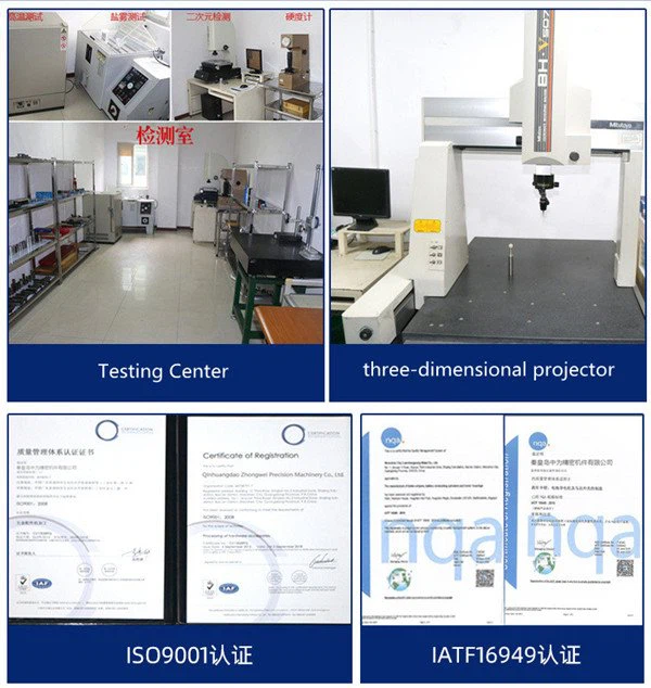
Metal Injection Molding Process

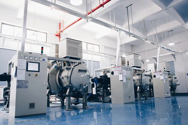
Detection Systems
Metal Injection Molding Process
Product Introduction
Toy Reels MIM Parts | |||||||||
Item | Material | Production Process | Sintering Temperature | Mold | Custom | ||||
Toy Reels | 17-4 | Metal Injection Molding | 1500℃ | To be customized | Yes | ||||
Chemical Composition | C:≤0.07 | ||||||||
Available Materials | Low carbon stainless steel, titanium alloy (Ti, TC4), copper alloy, tungsten alloy, hard alloy, high temperature alloy (718, 713) | ||||||||
Finish | Dimensional Accuracy | Product Density | Appearance Treatment | Appropriate Weight | |||||
Roughness 1~5μm | (±0.1%~±0.5%) | 92~95% | Mirror Reflection | 0.03g~400g) | |||||
Mechanical properties | Tensile strength σb (MPa): aged at 480°C, ≥1310; aged at 550°C, ≥1060; aged at 580°C, ≥1000; aged at 620°C, ≥930 | ||||||||
Production Method
A manufacturing method using Toy Reels MIM Parts

The utility model relates to the technical field of rotating shafts, in particular to a toy rotating shaft using a metal powder injection process.
Background technique
The rotating shaft, as the name implies, is the shaft that must be used to connect the main parts of the product and is used to bear both bending moment and torque in the rotating work. At present, the installation of most rotating shafts all adopts one-way insertion into the rotating shaft fixing bracket, and the knurling at the tail end of the rotating shaft is in interference fit with the inner wall of the through hole of the rotating shaft fixing bracket so that it will not fall out. But it is extremely difficult to remove after installation. Therefore, it is necessary to design a toy rotating shaft that adopts metal powder injection technology.
Technical Realization Elements
In view of the above situation, in order to overcome the defects of the prior art, the utility model provides a rotating shaft using metal powder injection technology. The rotating shaft has a novel structure, ingenious conception, good stability in use, convenient installation and disassembly, and convenient lubrication. long life.
In order to achieve the above purpose, the utility model provides the following technical solutions: a rotating shaft using metal powder injection technology, including a bearing bracket and a rotating shaft body, a through hole is opened at the center of one side of the inner wall of the bearing bracket, and the through hole The inside of the first bearing is rotatably connected with a first bearing, and the inside of the first bearing is clamped and fixed with an elastic limit mechanism. The center of the other side of the bearing bracket is rotatably connected with a second bearing, and one end of the shaft body passes through the The second bearing is fixed inside the elastic limit mechanism, the two sides of the second bearing on the bearing bracket are welded and fixed with a positioning screw, the positioning screw is fixed with a positioning sleeve through a nut, and the positioning sleeve is welded and fixed on the positioning On the corresponding two sides of the cover, the positioning cover is fixed on the other end of the rotating shaft body, and the bearing bracket is fixed with a lubricating mechanism on one side of the first bearing and the second bearing.
Preferably, the elastic limit mechanism includes a support spring, a square limit block and a hexagonal positioning hole, the square limit block is slidably connected to the inner wall of the first bearing, and the square limit block passes through the support spring and the bottom of the through hole The inner walls are connected, and a hexagonal positioning hole is opened at the center of the top of the square limiting block.
Preferably, one end of the rotating shaft body is integrally formed with a hexagonal joint, and the hexagonal joint is plugged and fixed inside the hexagonal positioning hole.
Preferably, the lubricating mechanism includes an oil storage tank, an oil pump, a timer, an oil outlet nozzle, an oil pipe and a nozzle bracket, the oil storage tank is fixed on the bottom side of the bearing bracket by bolts, and one side of the oil storage tank is fixed by bolts There is a timer, the bottom inner wall of the oil storage tank is provided with an oil pump, the bearing bracket is located on the side of the first bearing and the second bearing, and the nozzle bracket is fixed by bolts, and the oil outlet nozzle is fixed on the nozzle bracket by bolts , and the oil outlet nozzle is connected to the water outlet of the oil pump through the oil pipe, and the timer is electrically connected to the oil pump.
Preferably, an oil inlet hole is opened on one side of the oil storage tank, and a rubber sealing cover is clamped and fixed on the oil inlet hole.
Preferably, the shaft body is molded by metal powder injection process.
The beneficial effects of the utility model are:
1. When installing, pass the end of the shaft body with the hexagonal joint through the second bearing and fix it inside the hexagonal positioning hole, then connect the positioning sleeve on the positioning cover to the positioning screw, and use the nut to tighten it. During the tightening process of the cap, the support spring will be stressed and compressed. Under the reverse force of the support spring, the positioning cover can be firmly supported, thereby giving the nut a resisting force, so that the nut is fixed more tightly. When dismounting, loosen the nut, and the shaft body will pop out under the reverse force of the support spring, which is convenient for the quick disassembly of the shaft body and effectively improves the convenience of use;
2. Through the set timer, when the predetermined time is reached, the timer controls the oil pump to work, and the lubricating oil inside the oil storage tank is sprayed out through the oil outlet nozzle to lubricate the first bearing and the second bearing, thus realizing timing lubrication function, thereby effectively reducing the wear between workpieces and greatly improving the service life of the shaft.
Description of drawings
The accompanying drawings are used to provide a further understanding of the utility model, and constitute a part of the description, and are used to explain the utility model together with the embodiments of the utility model, and do not constitute a limitation to the utility model. In the attached picture:
Fig. 1 is a schematic diagram of the overall plane structure of the utility model;
Fig. 2 is a schematic diagram of the planar structure of the elastic limit mechanism of the utility model;
Fig. 3 is a schematic diagram of a three-dimensional structure of a hexagonal joint of the present invention;
Fig. 4 is a schematic diagram of the planar structure of the lubrication mechanism of the present invention;
Symbols in the figure: 1. Bearing bracket; 2. First bearing; 3. Elastic limit mechanism; 4. Through hole; 5. Shaft body; 6. Second bearing; 7. Positioning sleeve; 8. Nut; 9. Positioning cover; 10. Positioning screw; 11. Lubricating mechanism; 12. Support spring; 13. Square limit block; 14. Hexagonal positioning hole; 15. Hexagonal joint; 16. Oil storage tank; 17. Oil pump; 18. Timer; 19. Oil outlet nozzle; 20. Oil pipe; 21. Nozzle bracket; 22. Oil inlet hole.
Detailed ways
Below in conjunction with accompanying drawing 1-4, the specific embodiment of the present utility model is described in further detail.
Embodiment 1, shown in Figure 1, the utility model provides the following technical solutions: a rotating shaft using metal powder injection technology, including a bearing bracket 1 and a rotating shaft body 5, the center of one side of the inner wall of the bearing bracket 1 is open to see through Hole 4, the inside of through hole 4 is rotatably connected with first bearing 2, the inside of first bearing 2 is clamped and fixed with elastic limit mechanism 3, the center of the other side of bearing bracket 1 is rotatably connected with second bearing 6, and the rotating shaft One end of the body 5 passes through the second bearing 6 and is fixed inside the elastic limit mechanism 3, and the two sides of the second bearing 6 on the bearing bracket 1 are welded and fixed with a positioning screw 10, and the positioning screw 10 is fixed with a positioning screw 10 through a nut 8. 7, and the positioning sleeve 7 is welded and fixed on the corresponding two sides of the positioning cover 9, the positioning cover 9 is fixed on the other end of the rotating shaft body 5, and the bearing bracket 1 is fixed with a lubricating oil on one side of the first bearing 2 and the second bearing 6. Mechanism 11, when installing, pass one end of the hexagonal joint 15 of the rotating shaft body 5 through the second bearing 6 and fix it inside the hexagonal positioning hole 14, then the positioning sleeve 7 on the positioning cover 9 is sleeved on the positioning screw 10, and Use the nut 8 to tighten. During the tightening process of the nut 8, the support spring 12 will be stressed and compressed. Under the reverse force of the support spring 12, it can firmly withstand the positioning cover 9, thereby giving the nut The force of the cap 8 makes the nut 8 more tightly fixed, and when the nut 8 is unscrewed, the rotating shaft body 5 will also pop up under the reverse force of the support spring 12, which is convenient for the rotating shaft body 5 Quick disassembly effectively improves the convenience of use.
Embodiment 2, on the basis of Embodiment 1, given by Figure 1 and Figure 2, the elastic limit mechanism 3 includes a support spring 12, a square limit block 13 and a hexagonal positioning hole 14, and the square limit block 13 is slidably connected to the The inner wall of the first bearing 2, and the square limiting block 13 is connected with the bottom inner wall of the through hole 4 through the support spring 12, and the top center of the square limiting block 13 is provided with a hexagonal positioning hole 14.
Embodiment 3, on the basis of Embodiment 1, shown in FIG. 1 and FIG. 3 , one end of the rotating shaft body 5 is integrally formed with a hexagonal joint 15 , and the hexagonal joint 15 is plugged and fixed inside the hexagonal positioning hole 14 .
Embodiment 4, on the basis of Embodiment 1, given by Fig. 1 and Fig. 4, lubricating mechanism 11 includes oil storage tank 16, oil pump 17, timer 18, oil outlet nozzle 19, oil pipe 20 and nozzle bracket 21, oil storage tank 16 is fixed on the bottom side of the bearing bracket 1 by bolts, a timer 18 is fixed on one side of the oil storage tank 16 by bolts, an oil pump 17 is arranged on the inner wall of the bottom of the oil storage tank 16, and the bearing bracket 1 is located on the first bearing 2 and the second One side of the bearing 6 is fixed with a nozzle bracket 21 by bolts, and an oil outlet nozzle 19 is fixed on the nozzle bracket 21 by bolts, and the oil outlet nozzle 19 is connected to the water outlet of the oil pump 17 through the oil pipe 20, and the timer 18 is electrically connected to the oil pump 17 , through the set timer 18, when the predetermined time is reached, the timer 18 controls the oil pump 17 to work, and the lubricating oil inside the oil storage tank 16 is sprayed out through the oil outlet nozzle 19 to lubricate the first bearing 2 and the second bearing 6 , so as to realize the regular lubrication function, thereby effectively reducing the wear between the workpieces and greatly improving the service life of the shaft.
Embodiment 5. On the basis of Embodiment 4, as shown in FIG. 1 , one side of the oil storage tank 16 is provided with an oil inlet hole 22 , and a rubber sealing cover is clamped and fixed on the oil inlet hole 22 .
Embodiment 6, on the basis of Embodiment 1, the rotating shaft body 5 is molded by metal powder injection process.
When the utility model is used and installed, one end of the rotating shaft body 5 with the hexagonal joint 15 passes through the second bearing 6 and is fixed inside the hexagonal positioning hole 14, and then the positioning sleeve 7 on the positioning cover 9 is sleeved on the positioning screw rod 10 and use the nut 8 to tighten. During the tightening process of the nut 8, the support spring 12 will be compressed under force. Under the reverse force of the support spring 12, the positioning cover 9 can be firmly supported. Thereby giving the nut 8 a force to withstand, so that the nut 8 is fixed more tightly, and when dismounting, the nut 8 is loosened, and the shaft body 5 will also pop up under the reverse force of the support spring 12, which is convenient for the shaft The quick disassembly of the main body 5 effectively improves the convenience of use;
Through the set timer 18, when the predetermined time is reached, the timer 18 controls the oil pump 17 to work, and the lubricating oil inside the oil storage tank 16 is sprayed out through the oil outlet nozzle 19 to lubricate the first bearing 2 and the second bearing 6, In this way, the regular lubrication function is realized, which effectively reduces the wear between the workpieces and greatly improves the service life of the rotating shaft.
Finally, it should be noted that: the above is only a preferred embodiment of the utility model, and is not intended to limit the utility model, although the utility model has been described in detail with reference to the foregoing embodiments, for those skilled in the art , it is still possible to modify the technical solutions described in the foregoing embodiments, or perform equivalent replacements for some of the technical features. Any modification, equivalent replacement, improvement, etc. made within the spirit and principles of the present utility model shall be included in the protection scope of the present utility model.
Detection Systems
Metal Injection Molding Process



Send Inquiry
