



Razor MIM Parts
Shearing machine tool is a commonly used tool. The tool body is made of metal powder injection molding, and the material is tungsten steel. The current tool is installed on the shearing machine by screws.
Product Introduction
Razor MIM Parts | |||||||||
Item | Material | Production Process | Sintering Temperature | Mold | Custom | ||||
Razor | 17-4 | Metal Injection Molding | 1350-1500℃ | To be customized | Yes | ||||
Chemical Composition | C: 0.95~1.20 | ||||||||
Available Materials | Low carbon stainless steel, titanium alloy (Ti, TC4), copper alloy, tungsten alloy, hard alloy, high temperature alloy (718, 713) | ||||||||
Finish | Dimensional Accuracy | Product Density | Appearance Treatment | Appropriate Weight | |||||
Roughness 1~5μm | (±0.1%~±0.5%) | 92~95% | Mirror Reflection | 0.03g~400g) | |||||
Mechanical properties | Hardness: annealed, ≤269HB; | ||||||||
Heat treatment process | 1) Annealing, slow cooling at 800~920℃; | ||||||||
Production Method

The invention belongs to the technical field of cutting tools, in particular to a metal powder injection molding tungsten steel cutting tool assembly.
Background technique
Shearing machine tool is a commonly used tool. The tool body is made of metal powder injection molding, and the material is tungsten steel. The current tool is installed on the shearing machine by screws. However, since the bottom of the shearing machine is equipped with a conveyor belt, This leads to no installation space directly below the shearing machine, requiring two workers to lift the cutter body and fix it at both ends of the conveyor belt, which is troublesome to install.
Technical Realization Elements
Aiming at the deficiencies in the prior art, the present invention provides a metal powder injection molding type tungsten steel cutter assembly, and the specific technical scheme is as follows:
Metal powder injection molded tungsten steel tool assembly, including a fixed base, the bottom of the fixed base is rotatably connected to the movable base, the bottom of the movable base is inserted with a cutter body, and the outer end of the movable base is installed There is a blocking mechanism, which is used to stop the cutter body from the end.
Further, the middle part of the top surface of the movable base is vertically provided with a rotating column, and the rotating column is rotatably embedded in the fixed base, the top of the rotating column is provided with a gear, and the side wall of the fixed base is provided with In the installation groove, the gear is arranged horizontally, the gear protrudes from the installation groove, and the protruding part of the gear engages and connects with the driving mechanism.
Further, the drive mechanism includes a pneumatic rod and a tooth plate, the tooth plate is placed parallel to the side of the fixed base, the tooth plate is vertically meshed with the connecting gear, and the end of the tooth plate is fixedly connected to the pneumatic rod, so The pneumatic rod is fixed on the side of the fixed base.
Further, a slot is provided on the bottom surface of the movable base, the side section of the slot is inverted T-shaped, the inner end of the slot is a sealing structure, and the top surface of the cutter body is provided with a The cutting strip is slidably inserted into the slot, and the blocking mechanism stops at the outer end of the cutting strip.
Further, the blocking mechanism includes a blocking plate, a flexible blocking block and locking screws, the blocking plate is rotatably mounted on the end face of the movable base, and the inner wall of the blocking plate is provided with a flexible blocking block, The flexible blocking block is embedded in the slot and stops at the end of the cutting strip.
Further, both ends of the top surface of the movable base are provided with limiting slides, and both ends of the fixed base are provided with chute of rectangular through-hole structure, and the limiting slide slides through the chute.
Further, the limit slide plate includes an arc plate and a support plate, the arc plate slides through the chute, the arc plate is a circular arc structure, and both ends of the bottom surface of the arc plate are provided with support plates, the The support plate is fixedly connected to the movable base.
The beneficial effects of the present invention are:
1. The rotating movable base can make the movable base rotate 30-60° when installing the cutter body, and the insertion end of the movable base can be tilted to the side of the conveyor belt. At this time, the worker is on the side of the conveyor belt. , Just insert the cutter body directly into the movable base, the operation space is large, the installation is simple and efficient;
2. The rotating movable base can realize inclined cutting, which makes the application range of the shearing machine wider.
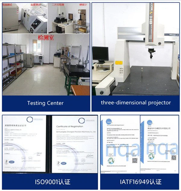
Detection Systems
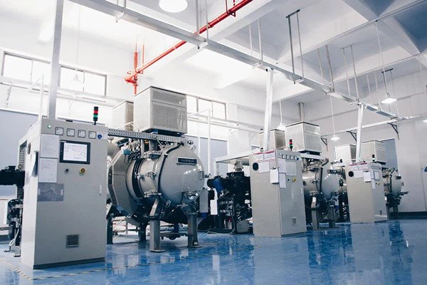
Metal Injection Molding Process




Send Inquiry
