



Micro Turbine MIM Parts
Core Tip: Metal Injection Molding (MIM) technology can manufacture materials that are difficult to process with other traditional processes into parts with complex structures. This feature makes it ideal for producing high-performance turbochargers
Product Introduction
Micro Turbine MIM Parts | |||||||||
Item | Material | Production Process | Sintering Temperature | Mold | Custom | ||||
Micro Turbine | 17-4 | Metal Injection Molding | 1350-1500℃ | To be customized | Yes | ||||
Chemical Composition | C:≤0.07 | ||||||||
Available Materials | Low carbon stainless steel, titanium alloy (Ti, TC4), copper alloy, tungsten alloy, hard alloy, high temperature alloy (718, 713) | ||||||||
Finish | Dimensional Accuracy | Product Density | Appearance Treatment | Appropriate Weight | |||||
Roughness 1~5μm | (±0.1%~±0.5%) | 92~95% | Mirror Reflection | 0.03g~400g) | |||||
Mechanical properties | Tensile strength σb (MPa): aged at 480°C, ≥1310; aged at 550°C, ≥1060; aged at 580°C, ≥1000; aged at 620°C, ≥930 | ||||||||
Core Tip: Metal Injection Molding (MIM) technology can manufacture materials that are difficult to process with other traditional processes into parts with complex structures. This feature makes it ideal for producing high-performance turbochargers
Metal Injection Molding (MIM) technology can manufacture those materials that are difficult to process with other traditional processes into parts with complex structures. This characteristic makes it an ideal method for producing high-performance turbocharger parts. BASF's unique Catamold process can help solve a series of key problems in the development of turbocharger MIM parts.
Turbocharger MIM Parts
The heart of a turbocharger is a turbine inside the turbine chamber, driven by the flow of hot exhaust gas, and a compression wheel on the cold air side. Compression impellers only need to withstand lower temperatures, and the performance of aluminum impellers can fully meet the requirements. The high-temperature exhaust gas in the turbine chamber requires the use of high-temperature resistant high-quality steel for the turbine. Turbine is usually produced by investment casting process. In theory, turbine can be manufactured by MIM process.
Metal Injection Molding (MIM) technology has been used in turbocharger parts for a long time. Due to the obvious advantages of MIM in material selection and design freedom, parts manufactured by MIM technology have been widely used in recent years, and its performance has been proved in actual use.
Challenges
Although MIM technology has made some progress, there are still a lot of work on process optimization, part structure and mold design to manufacture those parts that are almost demanding. When too much material accumulates in the central area of the turbine, it may cause the phenomenon of shrinkage cavity. This is due to volume shrinkage that occurs during cooling. Both processes have the potential for this defect to occur when the mold is filled with molten material (molten metal in investment casting, molten feed in MIM). The use of modern simulation techniques can be used for detailed analysis of this issue. For example, accurate prediction of MIM injection molding processes with the help of appropriate software. Figure 1 shows the effect of turbo simulated mold filling. This part uses a conical gate through which molten feedstock is injected into the part.
In addition to the mold and melt temperature, the mold filling process can be simulated very realistically by further adjusting the injection speed (cm3/s). Figures 1 and 2 show the process of turbine mold filling over time. Under the set conditions, the part is filled within 1.1s. The color temperature graph shows the change of the melt over time during the filling process. Blue areas are filled first, red areas last. By observing the cooling process of the part in the mold or after demoulding, it is possible to detect the subtle process of melt solidification in the defect area. Solidification pressure cross-sectional view of the turbine after cooling in the mold for 40 s. The larger blue area in the middle indicates that the pressure was very low at the end of cooling, while the adjacent area has solidified material, preventing further melt from entering. Therefore, the volume shrinkage in the blue region due to cooling of the material results in the creation of shrinkage cavities. Figure 4 clearly demonstrates this problem, where voids are caused by unsolidified material after the cooling time.
Lost core technology
In the Catamold process, after injection molding is complete, the acetal binder is quickly removed from the part by decomposing in an acidic environment in a debinding oven.
If a core is first injection molded with POM and then fed and overmolded around the core, parts with complex hollow structures can be obtained as the POM core is removed during debinding.
A cross-sectional view showing how an otherwise solid part is formed into a hollow interior by inserting a core during the injection molding process. As the core is removed after injection molding, a specific hollow structure will be formed.
Figure 6 shows the improvement effect of the lost core technology on the defect area of the turbine. The colored stripes represent the time required for each region to solidify. The parts of the part except the mold core are completely solidified after cooling for 27s.
Compared with the ordinary MIM process, the lost core method can significantly improve the production efficiency of parts. This is because, in theory, the mold core can be made into any shape, and the internal structure can be adjusted according to the actual size and load of the turbine. At the same time, this technology can also greatly reduce the weight of the turbine.
Sintering process
The final step in metal injection molding technology is sintering, during which the remaining binder is removed and the part shrinks in size. The temperature of sintering is slightly lower than the melting point of the alloy used, and the size change will be large during the process.
The shrinkage characteristics of MIM parts are affected by mold shape, long-term production stability, material batch variance, and processing window. In order to obtain a stable shrinkage rate, the production of molds, especially for parts with complex geometric structures, requires several rounds of optimization to correct the dimensions. Some of these dimensional changes are difficult to predict in advance and may be formed during injection molding or sintering.
It is not difficult to imagine that at a sintering temperature as high as 1200 ° C ~ 1450 ° C (according to different types of materials), parts with complex shapes are easily deformed. This distortion can in many cases be avoided through proper component design and process control.
However, the situation becomes more complicated when wall thickness, cantilever construction, and friction due to shrinkage combine to cause deformation.
Much in-depth fundamental research has been done in order to be able to predict in advance possible deformation and shrinkage differences, so that as much as possible, they can be eliminated by appropriate modification of the mold.
Modeling of Turbocharger Guide Vanes
Shown are the guide vanes of the turbocharger used during the sintering simulation. With the aid of the simulation software, the areas most prone to deformation can be identified. The sintering model described by Barriere was used here. In this model, the visible shrinkage of MIM parts is regarded as creep and described according to the characteristics of viscoelastic materials. The graph shows the shrinkage of Catamold 310N material over time (right scale) at two heating rates (left scale). Obviously, different heating rates lead to different shrinkage, which, combined with other reactions that occur during sintering, can lead to deformation of the part.
Shown on the left are the cross-linked guide vanes, with the lines indicating where they were when sintered. The comparison on the right shows the part before and after sintering, where the change in shape and position of the part can be clearly seen.
Based on the sintering model and the shrinkage properties of the material, the shrinkage of the part in the spatial direction can be calculated. Therefore, the shrinkage that occurs during sintering is shown. The color temperature plot clearly shows the tendency for regions to shrink and get smaller. Considering shrinkage along the axial direction, the dark blue represents the area with the greatest degree of shrinkage, and the yellow portion of the transition from the journal to the guide vane represents the area with the least shrinkage.
For comparison, the lay-flat sintering process of the guide vane was also simulated. The results obtained from the simulation make it possible to consider and take appropriate measures to eliminate anisotropic shrinkage during the development of the part.
raw material
Another core issue involved in the manufacture of MIM turbines is the availability of suitable materials. These materials are required to be able to withstand high temperatures of up to 1080°C under high loads. The key advantage of MIM is that it can make parts from materials that are difficult to machine by investment casting.
Superalloys have been used in MIM technology since 2003 and are widely known. In the selection of turbocharger impeller material, a basic requirement is to have high strength at high temperature. Figure 11 shows the fracture strength values of different materials after high temperature action for 1000h.
Due to the production of ultrafine powder, the microstructure of MIM superalloy parts is very uniform, which is quite different from that of precision cast parts. Inconel 713 C, a superalloy often used to make turbocharger parts, has also been developed as a MIM material.
Due to the relatively high content of aluminum and titanium, sintering of this material is not possible at all under the usual sintering atmospheres (hydrogen, nitrogen). However, it was found that the use of argon as a shielding gas prevents the oxidation of these elements during sintering and achieves effective control over shrinkage.
The direct comparison of the mechanical strength of MIM parts and investment casting samples at room temperature (attached table) proves that Catamold process can obtain excellent material properties.
Summarize
The turbocharger market will continue to show strong growth in the next few years, one of the reasons is the gradual increase in gasoline engine turbocharger applications.
Metal injection molding technology has proven to be one of the effective ways to produce complex parts for turbochargers, but the potential of MIM technology in molding has yet to be discovered.
With the application of injection molding and sintering process simulation technology, it is possible to further reduce the product optimization steps in the part development process. MIM technology provides sufficient guarantee for the use of high heat-resistant materials. Parts made of heat-resistant materials such as MIM superalloys have a very uniform microstructure, and their mechanical properties at room temperature even surpass those of investment casting parts.
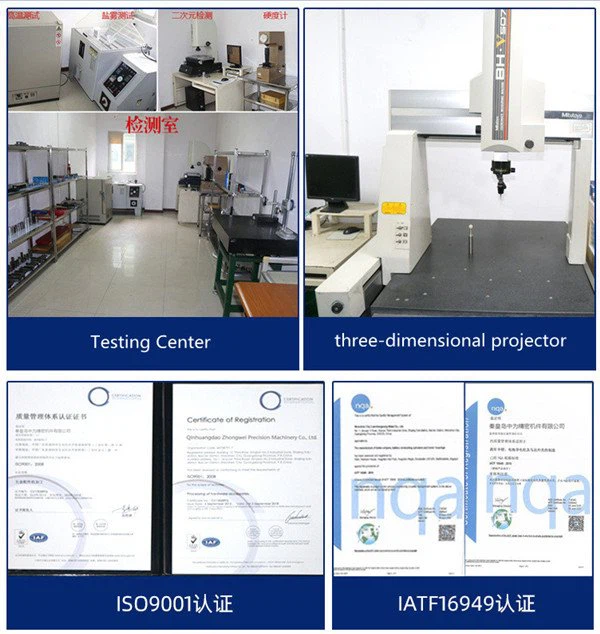
Detection Systems
Metal Injection Molding Process



Send Inquiry
