

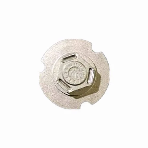


Car Mirror Mount MIM Parts
The exterior rearview mirror is an important part of the vehicle. Its function is to enable the driver to clearly observe the movement of the vehicle coming from behind to improve driving safety. At present, the exterior rearview mirror of the car is installed on both sides of the car, which is the outermost part of the car and the most vulnerable part.
Product Introduction
Item | Material | Production Process | Sintering Temperature | Mold | Custom | ||||||
Car Mirror Mount | 316L | Metal Injection Molding | 1350°C-1500°C | To be customized | Yes | ||||||
Chemical Composition | C :≤0.08 | ||||||||||
Available Materials | Low carbon stainless steel, titanium alloy (Ti, TC4), copper alloy, tungsten alloy, hard alloy, high temperature alloy (718, 713) | ||||||||||
Finish | Dimensional Accuracy | Product Density | Appearance Treatment | Appropriate Weight | |||||||
Roughness 1~5μm | (±0.1%~±0.5%) | 92~95% | Mirror Reflection | 0.03g~400g) | |||||||
Mechanical properties | Tensile strength σb (MPa): ≥480 | ||||||||||
Thermal conductivity (W/(m*K)) | 100℃ | 300℃ | 500℃ | ||||||||
15.1 | 18.4 | 20.9 | |||||||||
Heat treatment | Olid solution 1010 ~ 1150 ℃ rapid cooling. | ||||||||||
Manufacturing method of mirror base structure

The exterior rearview mirror is an important part of the vehicle. Its function is to enable the driver to clearly observe the movement of the vehicle coming from behind to improve driving safety. At present, the exterior rearview mirror of the car is installed on both sides of the car, which is the outermost part of the car and the most vulnerable part. Some accidents will inevitably occur during the driving process of the car. Car Mirror Mount MIM Parts are installed on the car The parts with the widest width are the most vulnerable to impact when they rub against each other. In order to avoid scratches to the greatest extent, the rearview mirror needs to have a folding function. The rearview mirror with folding function can be used when passing a narrow road Shrinking up improves the passability of the car. When the driver leaves the car, the rearview mirror can also be folded, which not only protects the mirror surface, but also reduces the parking space, effectively avoiding scratches.
At present, exterior rearview mirrors are mainly divided into electric folding exterior rearview mirrors and manually folding exterior rearview mirrors. Exterior rearview mirrors mainly include mirror seats and folders, and manual folding exterior rearview mirrors also include hinges and base plates. , wherein the structure of the rotating shaft is shown in Figure 1, a plurality of mounting protrusions 11 are provided at the tail of the rotating shaft 1, the structure of the base plate is shown in Figure 2, and there are multiple mounting protrusions 11 at the end of the base plate 2 for matching with the mirror holder. A card slot 21, when folding, the base plate is manually driven to rotate around the rotating shaft to realize the folding of the exterior rearview mirror. There is an installation part, and an installation hole is opened on the installation part. Since the manually foldable exterior rearview mirror also includes a rotating shaft and a base plate, the mirror seat structure of the electric folding exterior rearview mirror in the prior art does not have the rotation shaft and the base plate. The structural design of installation and position-limiting just makes the mirror seat of the manually foldable exterior rearview mirror need to carry out the structural design again, therefore, the mirror seat of the manually foldable exterior rearview mirror and the electric folding exterior rearview mirror of the prior art There are structural differences in the mirror bases of the mirrors, so that the mirror bases of the manual folding exterior mirrors and the mirror bases of the electric folding exterior mirrors need to be designed separately, which increases the mold cost and production cost, which is not conducive to The universal platform design of the mirror base.
Technical Realization Elements
Aiming at the above-mentioned deficiencies in the prior art, the technical problem to be solved by the utility model is: how to provide a device that can meet the installation requirements of the electric folding exterior mirror and the manual folding exterior mirror at the same time, thereby reducing mold and production costs, The mirror base structure of the automobile exterior rearview mirror is beneficial to the universal platform design of the mirror base.
In order to solve the above technical problems, the utility model adopts the following technical solutions:
A mirror base structure of an automobile exterior rearview mirror, comprising a mirror base, the mirror base is provided with a mounting part for connecting with a base plate and a rotating shaft, the mounting part is provided with a mounting hole, and the inner wall of the mounting hole is There is a limiting groove, and the rotating shaft can pass through the mounting hole and rotate around the mounting hole to a position where the mounting protrusion on the rotating shaft is snapped into the limiting groove, so as to pass through the limiting groove To limit the rotating shaft, a plurality of limit protrusions are also provided on the end surface of the installation part for matching with the base plate, and the base plate can move vertically along the limit protrusions, and the card slot on the base plate and the limit The positioning protrusion abuts against or breaks away from the position of the limiting protrusion, so that when the slot on the substrate is in contact with the limiting protrusion, the limiting protrusion can limit the rotation of the substrate, and the position on the substrate When the locking groove of the stopper is out of the position of the limiting protrusion, the base plate can rotate around the rotating shaft to realize the folding of the exterior rearview mirror.
In this way, when the mirror base structure of this solution is used on a manually folded exterior rearview mirror, the rotating shaft passes through the mounting hole and rotates around the mounting hole, so that the mounting protrusion on the rotating shaft is snapped into the limit groove at the corresponding position In this way, the limit of the rotation axis can be realized through the limit groove; at the same time, the substrate is moved downward along the limit protrusion. The rotation direction of the base plate can be restricted under the function of the limit protrusion. When the external rearview mirror needs to be folded, the base plate is moved upward along the limit protrusion. When the base plate moves, the limit protrusion is completely separated from the card of the base When the groove is formed, the base plate can be rotated along the rotating shaft without the limit of the limit protrusion at this time, and then the folding of the exterior rearview mirror can be realized. Therefore, the mirror seat structure of this solution can fully meet the installation and use of the manually folded exterior rearview mirror need.
At the same time, the mirror base structure of this program is improved on the mirror base structure of the electric folding exterior rearview mirror. When improving the mirror base of the electric folding exterior rearview mirror, on the one hand, the The size is increased, so that the shaft when installing the manually folded exterior rearview mirror can smoothly pass through the installation hole on the mirror base, and at the same time, a limit groove is set on the inner wall of the installation hole, and the limit groove is used to clamp The installation protrusion on the rotating shaft can realize the installation and limit of the rotating shaft; on the other hand, by increasing the thickness of the end face of the mirror base used to cooperate with the substrate, and adding a limit protrusion on the end face The base plate can be limited by the cooperation of the limit protrusion and the card slot on the base plate, and the base plate can also move upwards along the limit protrusion to a state where it can be rotated, thereby realizing the manual folding of the exterior rearview mirror. Folding purpose. Therefore, the mirror base structure of this program is an improvement on the mirror base structure of the electric folding exterior rearview mirror in the prior art. The improved mirror base structure is not only suitable for the electric folding exterior rearview mirror, but also suitable for manual folding. Therefore, the mirror base structure of this scheme can meet the installation requirements of electric folding and manual folding exterior mirrors at the same time. Only one mold needs to be opened during the production process of the mirror base, thus achieving the reduction of molds and For the purpose of production cost, it also utilizes the universal platform design of the mirror base.
Preferably, there are three limit protrusions in total, and the three limit protrusions are evenly distributed in the circumferential direction on the end surface of the mounting part for cooperating with the substrate.
In this way, the three position-limiting protrusions are evenly distributed in the circumferential direction on the end surface of the mounting part for cooperating with the substrate, so that the three position-limiting protrusions can limit the position of the substrate at three positions uniformly distributed in the circumferential direction, ensuring the position-limiting effect on the substrate. At the same time, it also corresponds to the position of the card slot on the substrate.
Preferably, both ends of the position-limiting protrusion along the circumferential direction are inclined-plane structures inclined outwards and downwards.
In this way, the inclined surface structure with both ends of the limiting protrusions inclined outward can provide a certain guiding effect for the movement of the substrate when the substrate moves, so that the substrate can be lifted or lowered along the inclined surface structure.
Preferably, a plurality of relief slots vertically penetrating through the installation hole are provided on the inner wall of the installation hole, and the inner diameter of the groove bottom of the relief slots is larger than the maximum outer diameter of the rotating shaft at the corresponding position, so that The rotating shaft can pass through the mounting hole through the relief slot.
In this way, since the rear part of the rotating shaft is provided with a mounting protrusion, the space required for the mounting protrusion when the rotating shaft passes through the mounting hole is provided by providing a relief groove, so as to ensure that the rotating shaft passes through the mounting hole smoothly.
Preferably, there are four relief grooves in total, and the four relief grooves are evenly distributed along the circumference of the installation hole.
In this way, the four relief slots correspond to the four mounting protrusions on the rotating shaft, so as to ensure that the rotating shaft passes through the mounting hole smoothly.
Preferably, a protrusion is formed between two adjacent relief grooves, and a limiting groove is provided on the lower end surface of the protrusion.
In this way, the limiting groove is arranged on the lower end surface of the protrusion, and when the rotating shaft passes through the mounting hole, the rotating shaft is rotated so that the installation protrusion on the rotating shaft rotates to the bottom of the limiting groove, and then moves upwards and rotates so that the rotating shaft The mounting protrusions on the top are clipped into the limit grooves at the corresponding positions, thereby realizing the limit of the rotation shaft.
Finally, it should be noted that the above embodiments are only used to illustrate the technical solution of the utility model rather than limit the technical solution. Those skilled in the art should understand that those who modify or replace the technical solution of the utility model without departing from The purpose and scope of the technical solution should be included in the claims of the utility model.
Metal Injection Molding Process

Detection Systems


Send Inquiry
