




Bevel Gear PM Sintered Part
The purpose of this utility model is to provide powder metallurgy high-density bevel teeth to solve the problem in the above background technology that when a certain drive tooth on the surface of the bevel tooth is affected by a gap due to long-term friction, the entire bevel can only be used. The problem can only be solved by replacing the teeth.
Product Introduction
|
Bevel gear PM sintered part |
||||||
|
Item |
Material |
Production Process |
Sintering Temperature |
Mold |
Custom |
|
|
Bevel gear powder metallurgy |
440c |
Metal Injection Molding |
1550℃ |
To be customized |
Yes |
|
|
Chemical composition |
C :0.95~1.20 Si: ≤1.00 Mn: ≤1.00 S : ≤0.030 P : ≤0.035 Cr:16.00~18.00 Ni:allowed to contain ≤0.60 |
|||||
|
Available Materials |
Low carbon stainless steel, titanium alloy (Ti, TC4), copper alloy, tungsten alloy, hard alloy, high temperature alloy (718, 713) |
|||||
Product advantages
|
Smoothness |
Dimensional accuracy |
Product density |
Appearance treatment |
Appropriate weight |
|
Roughness 1~5μm |
(±0.1%~±0.5%) |
92~95% |
Mirror reflection |
0.03g~400g) |
|
Mechanical properties |
Hardness: annealed, ≤269HB; Quenching and tempering, ≥58HRC Mechanical behavior: Internal stress (250 N/mm2) Tensile strength (560 N/mm2) EL(18%) HB(250) |
|||
|
Heat treatment |
1) Annealing, slow cooling at 800~920℃; 2) Quenching, oil cooling at 1010~1070℃; 3) Tempering, rapid cooling at 100-180°C; 4. Preheating temperature, 649°C-816°C. |
|||
Manufacturing method of powder metallurgy high-density bevel teeth
The utility model belongs to the technical field of gears, in particular to powder metallurgy high-density bevel gears.
Background technique:
Bevel gears are bevel gears, bevel gears, and bevel gears are most commonly used as the transmission of two vertical axes, but they are also suitable for transmission of two axes at other angles.
The existing ones still have some deficiencies when used:
1. When one of the transmission teeth on the surface of the bevel tooth has a gap due to long-term friction and affects the use, the problem can only be solved by replacing the entire bevel tooth. It is very troublesome to replace the entire gear and causes unnecessary waste.
2. When the external device is subjected to external force and vibrates and shakes, the bevel teeth inside the device may be detached, so that the transmission teeth are no longer engaged.
3. Long-term rotation of the transmission gear will cause wear and tear, resulting in damage to the bevel gear. There is no corresponding lubrication measure, and the lubricating oil can only be manually applied to the transmission gear, which is relatively complicated.
Technical realization elements:
The purpose of this utility model is to provide powder metallurgy high-density bevel teeth to solve the problem in the above background technology that when a certain drive tooth on the surface of the bevel tooth is affected by a gap due to long-term friction, the entire bevel can only be used. The problem can only be solved by replacing the teeth. It is very troublesome to replace the entire gear, and it causes unnecessary waste. When the external device receives external force and vibrates and shakes, the bevel gear inside the device may be detached. As a result, the drive teeth are no longer engaged, and the long-term rotation of the drive teeth will cause wear and tear, resulting in damage to the bevel teeth. Without corresponding lubrication measures, lubricating oil can only be manually applied to the drive teeth, which is a more complicated problem.
In order to achieve the above purpose, the utility model provides the following technical solutions: powder metallurgy high-density bevel teeth, including the first bevel teeth, the bottom of the first bevel teeth is provided with the second bevel teeth, and the first bevel teeth and the second bevel teeth Transmission teeth are evenly distributed on the surface of the teeth, a circular track is arranged inside one end of the first bevel tooth and the second bevel tooth, and two limit rods are provided at the connection between the first bevel tooth and the second bevel tooth, One end of the limit rod is provided with a circular movable block, and the circular movable block is inside the circular track, and the other end of the limit rod is provided with a connecting block, and the bolts pass through between the two limit rods. Internal fixed connections of connection blocks.
Preferably, the surface of the second bevel tooth is provided with a rectangular groove, and both sides of the rectangular groove are symmetrically provided with slide grooves, and the bottom ends of both sides of the transmission tooth are symmetrically provided with sliders, and the size of the slider is the same as that of the slider The grooves are matched, and the bottom of one end of the transmission tooth is provided with a fixed block. The transmission tooth, the slider, and the fixed block are of an integrated structure, and the transmission tooth is on the top surface of the second bevel tooth.
Preferably, oil passages are distributed inside the second bevel gear, and the number of oil passages matches the number of transmission teeth. One end of the oil passage communicates with the annular track, and a gap between every two transmission teeth is provided. The oil outlet, and the other end of the oil channel communicates with the oil outlet.
Preferably, the structural shapes of the first bevel teeth and the second bevel teeth are equal.
Preferably, the surface of the fixing block and one side surface of the second bevel tooth are both provided with corresponding bolt holes.
Preferably, the diameter of the circular movable block is 1.2 times the width of the circular track.
Compared with the prior art, the beneficial effects of the utility model are:
1. Due to the function of the limit rod, in the normal use process, it avoids the vibration and shaking of the external device under the action of external force, which may cause the bevel teeth inside the device to be detached. The movable block is inside the circular track, and the limit rod does not affect the rotation between the first bevel tooth and the second bevel tooth, and this method is stable and reliable.
2. Since each transmission tooth in this device is detachable, when a certain transmission tooth on the surface of the bevel tooth is damaged, a single transmission tooth can be disassembled and replaced, which solves the problem that when the transmission tooth of the original device is damaged, it can only be removed The problem can only be solved by replacing the entire bevel tooth, and the disassembly method is relatively simple, which avoids unnecessary waste.
3. Since there is an oil channel in the gap between the ring track and the transmission gear, and the ring track is filled with lubricating oil in advance, when the first bevel tooth and the second bevel tooth rotate, the ring will be moved under the action of the circular movable block. The lubricating oil in the track squeezes into the oil channel and flows to the gap between the transmission teeth, so as to achieve the effect of lubricating between the transmission teeth.
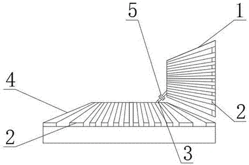
In the figure: 1. The first bevel tooth; 2. The transmission tooth; 3. The limit rod; 4. The second bevel tooth; 5. The connecting block; 6. The circular track; 7. The circular movable block; 8. The rectangular slot; 9, chute; 10, fixed block; 11, slide block; 12, oil channel.
Detailed ways
The technical solutions in the embodiments of the present invention will be clearly and completely described below in conjunction with the accompanying drawings in the embodiments of the present invention. Obviously, the described embodiments are only part of the embodiments of the present invention, not all of them. example. Based on the embodiments of the present utility model, all other embodiments obtained by persons of ordinary skill in the art without making creative efforts belong to the scope of protection of the present utility model.
Please refer to Figures 1 to 8, the utility model provides a technical solution: powder metallurgy high-density bevel teeth, including the first bevel teeth 1, the bottom of the first bevel teeth 1 is provided with the second bevel teeth 4, and the first bevel teeth 1 Transmission teeth 2 are evenly distributed on the surface of the second bevel tooth 4, and a circular track 6 is arranged inside one end of the first bevel tooth 1 and the second bevel tooth 4, and the connection between the first bevel tooth 1 and the second bevel tooth 4 There are two limit rods 3, one end of the limit rod 3 is provided with a circular movable block 7, and the circular movable block 7 is inside the circular track 6, and the other end of the limit rod 3 is provided with a connecting block 5, And the two limit rods 3 are fixedly connected through the interior of the connecting block 5 through bolts.
In order to facilitate disassembly of the transmission tooth 2, in this embodiment, preferably, the surface of the second bevel tooth 4 is provided with a rectangular groove 8, and both sides of the rectangular groove 8 are symmetrically provided with slide grooves 9, and the bottoms of both sides of the transmission tooth 2 A slider 11 is arranged symmetrically on the end, and the size of the slider 11 matches the chute 9, and a fixed block 10 is provided at the bottom of one end of the transmission tooth 2, and the transmission tooth 2, the slider 11, and the fixed block 10 are of an integrated structure, and The transmission tooth 2 is on the top surface of the second bevel tooth 4 .
In order that lubricating oil can flow into the gap between every two transmission teeth 2 from the annular track 6 and lubricate the transmission teeth 2, in this embodiment, preferably, the inside of the second bevel gear 4 is distributed with oil passages 12, and the oil passages The number of 12 matches the number of transmission teeth 2, one end of the oil channel 12 communicates with the annular track 6, an oil outlet is provided at the gap between every two transmission teeth 2, and the other end of the oil channel 12 communicates with the oil outlet .
In order to match the first bevel tooth 1 and the second bevel tooth 4 , in this embodiment, preferably, the structural shapes of the first bevel tooth 1 and the second bevel tooth 4 are equal.
In order to fix the transmission gear 2 under the action of the fixing block 10 , in this embodiment, preferably, the surface of the fixing block 10 and one side surface of the second bevel gear 4 are both provided with corresponding bolt holes.
Can not fall off from the circular track 6 for the circular movable block 7, the diameter of the circular movable block 7 is 1.2 times the width of the circular track 6.
The working principle and use process of the utility model: when the utility model is in use, the two limit rods 3 are first fixed through the inside of the connecting block 5 by bolts, and at this time the two limit rods 3 form a whole, and The circular movable block 7 at the two ends of the limit rod 3 is in the inside of the circular track 6, and the diameter of the circular movable block 7 is 1.2 times the width of the circular track 6, and the circular movable block 7 is between the first bevel tooth 1 and the second When the second bevel tooth 4 rotates, due to the action of the circular track 6, the limit rod 3 will not affect the rotation between the first bevel tooth 1 and the second bevel tooth 4, and at the same time avoid the vibration of the external device under the action of external force When shaking and shaking, the bevel gear inside the device may be detached. When the transmission gear 2 is damaged and needs to be replaced, the bolt on the surface of the fixing block 10 is removed, and the transmission gear 2 is pulled out from the inside of the rectangular groove 8, and Install the new transmission gear 2. When installing, align the sliders 11 on both sides of the transmission gear 2 with the chute 9 and push them in. After pushing to the bottom, use bolts to pass through the surface of the fixing block 10 and the second bevel gear 4. The bolt holes on the surface can be fixedly installed to complete the replacement of a single transmission tooth 2, which solves the problem that the transmission tooth 2 cannot be replaced individually when the transmission tooth 2 is damaged, and the entire bevel tooth needs to be disassembled and replaced. During the normal use of the first bevel tooth 1 and the second bevel tooth 4, because lubricating oil is filled into the interior of the ring track 6 in advance, the circular movable block 7 will move the ring when the first bevel tooth 1 and the second bevel tooth 4 rotate. The lubricating oil inside the track 6 is squeezed, so that the lubricating oil flows from the inside of the oil channel 12 into the gap between every two transmission teeth 2 , thereby lubricating the transmission teeth 2 .
Although the embodiments of the present invention have been shown and described, those skilled in the art can understand that various changes and modifications can be made to these embodiments without departing from the principle and spirit of the present invention , replacements and modifications, the scope of the present utility model is defined by the appended claims and their equivalents.
Metal Injection Molding Process

Detection Systems


Send Inquiry
