



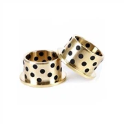
Shock Absorber Guide Seat PM Sintered Part
At present, the domestically produced shock absorbers with guide seats for automobiles or motorcycles have guide seat holes formed by extrusion, which require high processing technology and are not easy to guarantee: the connecting rod is easy to wear during reciprocating motion, and the lip of the oil seal is worn. Or scratched, forming shock absorber oil leakage.
Product Introduction
|
Shock absorber guide seat PM sintered part |
||||||
|
Item |
Material |
Production Process |
Sintering Temperature |
Mold |
Custom |
|
|
Shock absorber guide seat |
42crmo |
Powder metallurgy |
1280℃ |
To be customized |
Yes |
|
|
Chemical composition |
C :0.38~0.45% Si:0.17~0.37% Mn:0.50~0.80% S :Allowable residual content ≤0.035% P :Allowable residual content ≤0.035% Cr:0.90~1.20% Ni:Allowable residual content ≤0.30% Cu:Allowable residual content ≤0.30% Mo:0.15~0.25% |
|||||
|
Available Materials |
Low carbon stainless steel, titanium alloy (Ti, TC4), copper alloy, tungsten alloy, hard alloy, high temperature alloy (718, 713) |
|||||
Product advantages
|
Smoothness |
Dimensional accuracy |
Product density |
Appearance treatment |
Appropriate weight |
|
Roughness 1~5μm |
(±0.1%~±0.5%) |
92~95% |
mirror reflection |
0.03g~400g) |
|
mechanical properties |
Hardness: annealed, 147~241HB 42CrMo mechanical properties: Tensile strength σb (MPa): ≥1080(110) Yield strength σs (MPa): ≥930(95) Elongation δ5 (%): ≥12 Reduction of area ψ (%): ≥45 Impact energy Akv (J): ≥63 Impact toughness value αkv (J/cm2): ≥78(8) Hardness: ≤217HB |
|||
Bushing shock absorber guide seat
1. Technical field:
The utility model relates to a shock absorber used on automobiles or motorcycles, in particular to a bushing type guide seat shock absorber.
2. Background technology:
At present, the domestically produced shock absorbers with guide seats for automobiles or motorcycles have guide seat holes formed by extrusion, which require high processing technology and are not easy to guarantee: the connecting rod is easy to wear during reciprocating motion, and the lip of the oil seal is worn. Or scratched, forming shock absorber oil leakage.
3. Contents of the invention:
The purpose of this utility model is to provide a bushing type guide seat shock absorber, by changing the connection relationship between the guide seat and the connecting rod in the shock absorber, the problems of high processing technology requirements and difficult quality control of the inner hole of the guide seat are solved.
The specific scheme of the utility model is: a bushing type guide seat shock absorber, a connecting rod combination extends into the working cylinder combination, an oil storage cylinder combination is set outside the working cylinder combination, and the connecting rod of the connecting rod combination The upper loop has a guide seat, the guide seat is located at the port of the working cylinder combination, an oil seal is pressed between the guide seat and the port of the oil cylinder combination, and a shock absorbing spring is set on the outer cover of the oil cylinder combination and the connecting rod combination, The tail end of the damping spring is fixedly connected to the joint, and it is characterized in that: a bush is pressed into the inner hole of the guide seat, and the guide seat is looped on the connecting rod of the connecting rod assembly through the bush.
With the above solution, the surface of the inner hole of the guide seat is no longer used as a working surface for dynamic cooperation with the connecting rod, which reduces the difficulty of process and quality control in the processing of the inner hole of the guide seat. At the same time, the friction coefficient between the shock absorber guide seat combination and the working surface of the connecting rod surface moving in relative motion is reduced, the frictional resistance of movement is reduced, and the service life of the connecting rod and the oil seal is increased.
4. Description of drawings:
Fig. 1 is a schematic diagram of the overall structure of the utility model, which is also an embodiment of the utility model.
5. Specific implementation methods:
As shown in Figure 1: the utility model is mainly composed of a connecting rod 1, a working cylinder combination 2, an oil storage cylinder 3, a guide seat 4, a bushing 5, an oil seal 6, a damping spring 7, and a joint 8; the connection between them The relationship is that there is a connecting rod combination 1 extending into the working cylinder combination 2, an oil storage cylinder combination 3 is set on the working cylinder combination 2, and a guide seat 4 is looped on the connecting rod of the connecting rod combination 1, and the guide seat 4 is located at The port of the working cylinder combination 2 is press-fitted with an oil seal 6 between the guide seat 4 and the port of the oil cylinder combination 3, and the shock absorbing spring 7 is set on the outer cover of the connecting rod of the oil cylinder combination 3 and the connecting rod combination 1, and the shock absorbing spring The tail end of 7 is fixedly connected to joint 8; the main points of the structure of the utility model are: a bushing 5 is installed in the inner hole of the guide seat 4, and the guide seat 4 is looped on the connecting rod of the connecting rod assembly 1 through the bushing 5 . Form the moving fit working surface of the connecting rod surface of the connecting rod assembly 1 and the inner surface of the bushing 5 of the guide seat assembly.
The utility model works like this: under the action of external force, the oil storage cylinder 3 drives the working cylinder 2 to move to the left, forcing the damping oil of the working cylinder to generate compression resistance through the resistance hole. At this time, the shock absorbing spring 7 is compressed, When the shock-absorbing spring 7 returns to its original length, the force acts on the oil storage cylinder combination 3, making the working cylinder combination 2 and the oil storage cylinder combination 3 move to the right, so that the shock-absorbing oil of the oil storage cylinder combination 3 enters through the resistance hole. In the working cylinder combination 2, there is a restoring resistance; in the whole process of the reciprocating movement, the surface of the connecting rod on the connecting rod combination 1 and the inner surface of the inner hole bushing 5 of the guide seat 4 form a dynamic fit working surface, because the inner surface of the bushing The hole is sprayed with composite material, which is wear-resistant and smooth, and ideally solves the friction between the connecting rod on the connecting rod assembly 1 and the guide seat 4 and bushing 5 during the movement process to form a guide seat combination, and the wear of the connecting rod is minimal, and the corresponding It protects the oil seal, so the service life of the shock absorber is greatly improved.
Metal Injection Molding Process

Detection Systems


Send Inquiry
