


Automotive Sensor Mounts MIM Parts
Tensile strength σb (MPa): ≥480
Conditional yield strength σ0.2 (MPa): ≥177
Elongation δ5 (%): ≥40
Reduction of area ψ (%): ≥60
Product Introduction
Automotive Sensor Mounts MIM Parts | |||||||||||
Item | Material | Production Process | Sintering Temperature | Mold | Custom | ||||||
Car Sensor Bracket | 316L | Metal Injection Molding | 1350°C-1500°C | To be customized | Yes | ||||||
Chemical Composition | C :≤0.08 | ||||||||||
Available Materials | Low carbon stainless steel, titanium alloy (Ti, TC4), copper alloy, tungsten alloy, hard alloy, high temperature alloy (718, 713) | ||||||||||
Finish | Dimensional Accuracy | Product Density | Appearance Treatment | Appropriate Weight | |||||||
Roughness 1~5μm | (±0.1%~±0.5%) | 92~95% | Mirror Reflection | 0.03g~400g) | |||||||
Mechanical properties | Tensile strength σb (MPa): ≥480 | ||||||||||
Thermal conductivity (W/(m*K)) | 100℃ | 300℃ | 500℃ | ||||||||
15.1 | 18.4 | 20.9 | |||||||||
Heat treatment | Olid solution 1010 ~ 1150 ℃ rapid cooling. | ||||||||||
Product Analysis
This case is a bracket on a sensor of a car. The precision requirement is very high, the material is 316, the product is very small, the longest dimension is 38mm, and metal inserts (copper sheets) are also placed during injection molding, and the deformation is required to be small, as shown in Figure 1.

Figure 1
The non-concentricity of the upper and lower holes of this product Automotive Sensor Mounts MIM Parts is less than 0.02mm. Since POM (polyoxymethylene) products are prone to deformation, in order to minimize the internal stress of the product, the glue point The selection of the position should be fully considered in the mold design, and the upper and lower holes should be shaped after the mold is released, as shown in Figure 2.

Figure2
There is an undercut in the gap between the upper and lower holes, and the core must be pulled in two directions before the mold can be released, which brings certain difficulties to the design of the slider, as shown in Figure 3.

Figure3
The core should also be pulled in this direction, as shown in Figure 4.

Figure4
When injection molding, an insert should be put into the moving mold. The insert is a copper sheet with good elasticity, as shown in Figure 5.

Figure 5
In order to prevent the copper sheet from being offset by the plastic during injection molding, two small holes are set on the copper sheet, and corresponding cores are set in the mold to position them, as shown in Figure 6.

Figure 6
Gate design
After analysis, in order to reduce the stress of the product and minimize the deformation, the best position of the glue point is here, as shown in Figure 7.

Figure 7
I used the form of point gate, see Figure 8.

Figure 8
Mold flow analysis is provided by Moldex 3D company, see Figure 9.

Figure 9
Due to the tight space, the gate I designed interferes with the fixed mold pins, which is very difficult to deal with. Therefore, I canceled the fixed mold pins, and I used the original core for forming the fixed mold perforation. , see Figure 10.

Figure 10
This can leave a reasonable position for the gate tie rod, see Figure 11.

Figure 11
The overall structure of the mold adopts a simplified small nozzle structure, and adopts a first reset device, as shown in Figure 12.

Figure 12
Parting
Lower mold kernel and three slide blocks are arranged like this, see Fig. 13.

Figure 13
Hidden and lower mold kernels look like this in reverse, as shown in Figure 14.

Figure 14
Front mold core is designed like this, see Fig. 15.

Figure 15
Slider design
This set of models does not seem complicated, but the design of the slider is still a bit difficult, and all aspects of the relationship must be taken into account. First look at slider 1, see Figure 16.

Figure 16
The relationship between slider 1 and slider 2 is shown in Figure 17.

Figure 17
Since slider 1 and slider 2 and their common boundary is the sealing surface, it should be processed into a unified plane here, and there must be a draft slope, which is inserted into the fixed mold. Moreover, the mating surface should be very precise, so that the bonding line on the surface of the product should be as small as possible, as shown in Figure 18.

Figure 18
All the mating surfaces where the sliders are inserted into the mold should be sloped in the direction of motion to prevent the mating surfaces of the sliders and the mold from being rough due to friction, see Figure 19.

Figure 19
The design of slider 3 is shown in Figure 20.

Figure 20
The end face of the slider 3 touches the moving mold core to form a sealing position, and the mating surface extending into the mold core has a 3° slope in the direction of movement to ensure that the slider will not be damaged by friction during long-term work. And the hairy.
Fixed mold design
The power source of the slider is that the three inclined guide pillars push the slider apart through the mold opening force of the injection molding machine, and the inclined guide pillars are fixed on the fixed template by using the inclined guide pillar fixing blocks. The side of the fixed mold is provided with a plunger with a reset-first structure, as shown in Figure 21.

Figure 21
The layout of the moving model
The structure of this set of molds is very compact, and the standard 1515 simplified small nozzle mold base is used, as shown in Figure 22.

Figure 22
After the mold is opened, it looks like this before ejection, as shown in Figure 23.

Figure 23
The force to break the gate depends on the three nylon pull studs in the above picture. In order to make the reset force more balanced, the position of the reset lever is also carefully arranged.
Design of ejector mechanism
In order to reduce the internal stress of the product and minimize the deformation, I used more ejector pins to make the ejection force of each part of the product relatively balanced. A total of 10 ejector pins are used, which is really rare for such a small product, as shown in Figure 24.

Figure 24
Since five ejector pins interfere with the slide block, a first-reset structure must be provided, as shown in Figure 25.
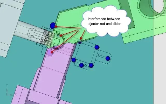
Figure 25
Design of first reset mechanism
Now let me introduce one of the most common pre-reset mechanisms, see Figure 26.
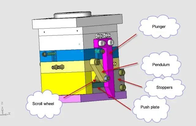
Figure 26
The first reset mechanism is also called the pre-reset mechanism, which is composed of four large parts: inserting rod, swing rod, roller and stopper. When the mold is opened, the inclined guide post will push the slide block apart completely, as shown in Figure 27.

Figure 27
Since the plunger has been pulled out, the pendulum has room to rotate. When the top column of the injection molding machine pushes the push plate, due to the action of the roller, the pendulum rotates along the pin axis (15 degrees here), see Figure 28.

Figure 28
The first reset mechanism is arranged on both sides of the mould, which is completely symmetrical, as shown in Figure 29.

Figure 29
Design of cooling water circuit
Since the product is relatively small, and inserts (copper sheet) should be placed in the gap of injection molding, the cycle of injection molding is relatively long, so the cooling water channel requirements of this set of molds are not high. I adopted the most simplified design, because the mold core is relatively small , the water is taken directly from the formwork. Fixed mold is 2 straight waterways, see Fig. 30.

Figure 30
The dynamic model is also like this, see Figure 31.

Figure 31
The design points of this set of molds are the arrangement of the boundaries of slider 1 and slider 2 and the selection of the position of the glue inlet.
Metal Injection Molding Process

Detection Systems


Send Inquiry