




Lock Body Drive Gear PM Parts
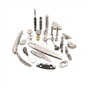
The original one-speed or two-speed mechanical lock body is equipped with a fully automatic mechanism, which causes the lock cylinder to jam and jump when the lock cylinder is opened or retracted, resulting in the lock body not being retracted or opened normally. Therefore, it is necessary to design a new first-speed gear transmission Lock Body Drive Gear PM Parts to solve the problems in the above-mentioned background technology.
Product Description
|
Lock Body Drive Gear PM Parts |
|||||
|
Item |
Material |
Production Process |
Sintering Temperature |
Mold |
Custom |
|
Lock Body Drive Gear |
440c |
Powder metallurgy sintering |
1550°C |
To be customized |
Yes |
|
Chemical composition |
C: 0.95~1.20 Si: ≤1.00 Mn: ≤1.00 S : ≤0.030 P : ≤0.035 Cr: 16.00~18.00 Ni: allowed to contain ≤0.60 |
||||
|
Available Materials |
Low carbon stainless steel, titanium alloy (Ti, TC4), copper alloy, tungsten alloy, hard alloy, high temperature alloy (718, 713) |
||||

1. The utility model relates to the field of lock body technology, specifically a new type of first gear transmission lock body.
Background technique:
2. The original one-speed or two-speed mechanical lock body is equipped with a fully automatic mechanism, which causes the lock cylinder to jam and jump when the lock cylinder is opened or retracted, resulting in the lock body not being retracted or opened normally.
3. Therefore, it is necessary to design a new first-speed gear transmission Lock Body Drive Gear PM Parts to solve the problems in the above-mentioned background technology.
Technical realization elements:
4. The purpose of this utility model is to provide a new first-speed gear transmission lock body to solve the problems raised in the above-mentioned background technology.
5. In order to achieve the above object, the utility model provides the following technical solutions:
6. A new type of first-gear gear transmission lock body, including a lock box, a guide plate is provided on one side of the lock box, and multiple sets of bolt heads are arranged in the middle of the guide plate, and the bolt heads are close to the side of the lock box There are three bolt plates, the upper and lower ends of the three bolt plates are provided with the push rivets of the sky and earth rods, and the sky and earth rods are connected to the push rivets of the sky and earth rods, and the side of the three bolt plates far away from the guide plate is connected with the three bolt dials , the three-bolt shifting plate is provided with a three-bolt shifting gear plate rivet near the three-bolt plate, and the upper end of the lock box is provided with two sets of lock cylinder dial fixing pieces near the lock cylinder, and the two sets of lock cylinder dials are fixed There is a lock cylinder toggle gear plate between the plates, and the upper end of the three-bolt dial is far away from the three-bolt plate. A lower gear plate is provided at the lower end of one side close to the fixed plate of the lock cylinder dial, and a starting plate is provided on the side of the three-bolt dial far away from the upper gear plate and the lower gear plate, and a dial shaft is arranged in the middle of the starting plate. , the side of the dial shaft away from the three-bolt dial is provided with a latch tongue, the side of the latch tongue far away from the guide plate is provided with a latch tongue pick, and the start plate is provided with a start plate rivet near the three-bolt dial , the upper gear disc is provided with an upper gear disc rivet, the lower gear disc is provided with a lower gear disc rivet, and a peg plate guide rivet is connected between the upper gear disc and the lower gear disc, and the three-bolt dial A peg plate return spring is connected near the starting plate.
7. As a preferred solution of the present utility model, the three-bolt plate, the sky-earth rod push rivet and the bolt head form a three-bolt assembly.
8. As a preferred solution of the present utility model, circular arc notches are provided on the two sets of lock cylinder thumb wheel fixing pieces, and the lock cylinder toggle gear disc and the arc notch are socketed and connected, and the two groups The lock cylinder thumb wheel fixing piece is riveted with the lock box and the lock cover above the lock box by rivets.
9. As a preferred solution of the present invention, the lock cylinder toggle gear plate is engaged with the upper gear plate.
10. As a preferred solution of the present invention, the side of the three-bolt dial close to the upper gear plate and the three-bolt plate close to the rivets of the three-bolt toggle gear plate are provided with notches.
11. As a preferred solution of the present utility model, the activation plate and the dial shaft are socketed and connected.
12. Compared with the prior art, the beneficial effects of the utility model are:
13. In this utility model, the gear plate is driven by the set lock core, and the lock core is used to drive the gear plate inside the lock body to drive the transmission of the lock body, which avoids the original one-speed or two-speed mechanical lock. The body is fully automatic, causing the lock cylinder to jam and jump when it is pushed out or retracted, which solves the problem that the lock body cannot be retracted or retracted normally.
Detailed ways
19. The technical solutions in the embodiments of the present invention will be clearly and completely described below in conjunction with the accompanying drawings in the embodiments of the present invention. Obviously, the described embodiments are only part of the embodiments of the present invention, not all Based on the embodiments of the present utility model, all other embodiments obtained by persons of ordinary skill in the art without making creative efforts belong to the scope of protection of the present utility model.
20. In order to facilitate the understanding of the utility model, the utility model will be described more fully below with reference to the accompanying drawings. Several embodiments of the utility model are shown in the accompanying drawings, but the utility model can be implemented in many different forms Implementation is not limited to the embodiments described herein, on the contrary, the purpose of providing these embodiments is to make the disclosure of the present utility model more thorough and comprehensive.
21. It should be noted that when an element is said to be “fixed on” another element, it may be directly on the other element or there may be an intervening element. When an element is referred to as being "connected to" another element, it can be directly connected to the other element or intervening elements may also be present. The terms "vertical," "horizontal," "left," "right," and similar expressions are used herein for purposes of illustration only.
22. Unless otherwise defined, all technical and scientific terms used herein have the same meaning as commonly understood by a person skilled in the technical field of the present invention. The terminology used in the description of the utility model herein is only for the purpose of describing specific embodiments, and is not intended to limit the utility model. As used herein, the term "and/or" includes any and all combinations of one or more of the associated listed items.
23. Please refer to Figure 1-4. This utility model provides a technical solution:
24. A new type of first-gear gear transmission lock body, including a lock box 16, a guide plate 17 is provided on one side of the lock box 16, and a plurality of groups of bolt heads 21 are arranged in the middle of the guide plate 17, and the bolt heads 21 are close to one side of the lock box 16. The side is provided with three bolt plates 14, and the upper and lower ends of the three bolt plates 14 are provided with heaven and earth rods to push rivets 15, and the sky and earth rods push rivets 15 to be connected with sky and earth rods 19, and the side of the three bolt plates 14 away from the guide plate 17 is connected with three bolts Dial plate 12, three-bolt dial 12 is provided with three-bolt shifting gear disc rivet 13 near the three-bolt plate 14, and two groups of lock cylinder dial fixing pieces 8 are arranged on the upper end of lock box 16 near the lock cylinder, two groups of lock cylinder dials A lock cylinder toggle gear plate 9 is arranged between the wheel fixed pieces 8, and an upper gear plate 11 is arranged at the upper end of the side upper end of the three-bolt dial 12 away from the three-bolt plate 14 near the lock cylinder dial fixed piece 8, and the three-bolt dial 12 The lower end of one side away from the three-bolt plate 14 is provided with a lower gear plate 6 near the lock cylinder dial fixed piece 8, and the side of the three-bolt dial 12 away from the upper gear plate 11 and the lower gear plate 6 is provided with a starting plate 3, A dial shaft 2 is provided in the middle of the activation plate 3, and the activation plate 3 and the dial shaft 2 are socketed and connected. The side of the dial shaft 2 away from the three-bolt dial 12 is provided with a latch tongue 1, and the latch tongue 1 is far away from the side of the guide plate 17. One side is provided with a slanted tongue paddle 5, and the starting plate 3 is provided with a starting plate rivet 4 near the three-bolt dial 12, and the upper gear plate 11 is provided with an upper gear plate rivet 10, and the lower gear plate 6 is provided with a lower gear Disk rivets 7, peg plate guide rivets are connected between the upper gear disk 11 and the lower gear disk 6
18. The three-bolt shifting plate 12 is connected with a peg plate return spring 20 near the starting plate 3 .
25. Embodiment, the three-bolt plate 14, the rivet 15 driven by the sky-earth rod and the bolt head 21 form a three-bolt assembly, which can move synchronously.
26. In the embodiment, the two groups of lock cylinder dial fixing pieces 8 are provided with arc notches, and the lock cylinder toggle gear plate 9 is socketed and connected with the arc grooves, and the two sets of lock cylinder dial fixing pieces 8 and the lock box 16 and the lock cover above the lock box 16 are all riveted by rivets, and the lock core to toggle the gear plate 9 and the upper gear plate 11 are meshed and connected, and the lock core is used to stir the inner lock core of the lock body to turn the gear plate. Drive the transmission of the lock body, avoiding the phenomenon that the original one-speed or two-speed mechanical lock body is equipped with full-automatic, causing the lock cylinder to be jammed and jumping out, and solve the problem that the lock body cannot be retracted or opened normally.
27. Embodiment, the side of the three-bolt dial 12 close to the upper gear plate 11 and the side of the three-bolt plate 14 close to the rivet 13 of the three-bolt toggle gear plate are provided with notches, so that the three-bolt dial 12 can follow the upper gear The promotion of the disc rivet 10 moves, so that the three-bolt plate 14 can move with the promotion of the three-bolt toggle gear disc rivet 13 .
28. Working principle: The transmission process during use is: key to close the door: the key rotates counterclockwise, and after a 30° idle travel, it drives the lock cylinder of the lock body to turn the gear plate 9 to rotate counterclockwise together, and the lock cylinder turns the gear plate 9 It can only be rotated along the arc notch of the lock core dial fixed piece 8, and the lock cylinder dial fixed piece 8 is respectively fixed on the lock cover of the lock box. When the lock cylinder moves the gear plate 9, the upper gear plate meshed with it 11 rotates clockwise around the peg plate guide rivet 18 in the middle, and at the same time the upper gear plate rivet 10 riveted on the upper gear plate 11 will rotate accordingly, and by cooperating with the left side of the notch of the three-bolt dial 12, the rotational force Transfer to the three-bolt dial 12, so that the three-bolt dial 12 also rotates clockwise around the guide rivet 18 of the bolt board, and at the same time, the three-bolt shifting gear disc rivet 13 riveted on the three-bolt dial 12 follows the three-bolt dial 12 rotate clockwise together, the three-bolt toggle gear plate rivet 13 will have an upward and rightward displacement during the rotation, and through the notch on the three-bolt plate 14, the three-bolt plate 14 will be pushed out of the lock, The three-bolt assembly can only move in two directions up and down, that is, the three-bolt assembly is shot out, and at the same time as the three-bolt assembly is shot out, the rivet 15 is driven by the upper and lower ends of the three-bolt plate 14 to drive the upper and lower two sky-earth rods 19 respectively. Stretch out, when the key is rotated to 90°, the three-bolt assembly is fully opened, and the two heaven and earth rods 19 are fully extended synchronously. The dead point of the movement of the plate 14 ensures that the three-bolt plate 14 will not be retracted due to external force, thereby realizing a reliable function of closing and locking the door.
29. Key to open the door: the key rotates clockwise for 30° idle travel, and then touches the lock cylinder to turn the gear plate 9, so that the lock cylinder turns the gear plate 9 to rotate clockwise together, and the lock cylinder turns the gear plate 9 to simultaneously make the upper gear plate 11 And the lower gear disc 6 rotates counterclockwise, and the upper gear disc 11 rotates to make the upper gear disc rivet 10 push the three-bolt dial 12, and the three-bolt toggle gear disc rivet 13 will leave the dead point of motion, and at the same time drive the three-bolt plate during the rotation process 14 is retracted to the inside of the lock body, and the three-bolt plate 14 pushes the rivet 15 through the sky-earth rod so that the two sky-earth rods 19 are retracted synchronously, and the lower gear plate 6 rotates clockwise, driving the lower gear plate rivet 7 riveted with it to rotate synchronously, and the lower gear The disc rivet 7 moves the tail of the latch bolt 5, so that the latch bolt 5 rotates clockwise around the dial shaft 2, and at the same time, the head of the latch bolt 5 moves the latch bolt 1, so that the latch bolt 1 is retracted into the lock body, After the key rotates clockwise to 90°, the retraction actions of the three bolt assemblies, the oblique tongue 1, and the heaven and earth rod 19 are completed synchronously, and the door can be pushed open this moment, and the door opening action is completed.
30. Handle to close the door: Turn the handle counterclockwise, that is, the dial shaft 2 rotates counterclockwise, and at the same time make the activation plate 3 sleeved on the dial shaft 2 rotate counterclockwise, the activation plate rivet 4 is riveted on the activation plate 3, and the activation plate rivet 4 is turned Move the three-bolt dial 12 to rotate clockwise around the guide rivet 18 of the three-bolt dial, and at the same time, the three-bolt shifting gear plate rivet 13 riveted on the front end of the three-bolt dial 12 rotates clockwise along with the three-bolt dial 12, and the three-bolt The rivet 13 of the toggle gear plate will have an upward and rightward displacement during the rotation process, and through the cooperation of the notches on the three-bolt plate 14, the three-bolt assembly will be pushed out of the lock, that is, the three-bolt assembly will be driven out, and the three-bolt assembly will be pushed out. While playing, push the rivets 15 through the heaven and earth rods riveted on the upper and lower ends of the three-bolt plate 14 to drive the upper and lower heaven and earth rods 19 to stretch out, and when the handle is rotated to 45°
Afterwards, it will not be able to continue to rotate, indicating that the three bolt assemblies and the heaven and earth rod 19 have been fully driven out at this time, and the door closing action is completed.
31. Open the door with the handle: Turn the handle clockwise to make the dial shaft 2 rotate clockwise synchronously. The clockwise rotation of the dial shaft 2 will drive the activation board 3 on it to rotate clockwise together, and the activation board riveted on the activation board 3 at the same time The rivet 4 pushes the three-bolt dial 12, so that the three-bolt dial 12 rotates counterclockwise around the bolt plate to guide the rivet 18, and at the same time, the three-bolt toggle gear plate rivet 13 pushes the three-bolt plate to the inside of the lock body through the notch of the three-bolt plate 14 To retract, push the rivets 15 riveted on the upper and lower ends of the three-bolt plate 14 to push the rivet 15 to simultaneously push the two-day rod 19 to retract. When the dial shaft 2 rotates clockwise, it will drive the oblique tongue pick 5 to rotate clockwise together, and the oblique tongue pick 5 Turn the latch bolt 1 clockwise to retract the latch bolt 1 to the inside of the lock body. When the handle cannot continue to rotate, turn it about 45°, indicating that the latch bolt 1 and the three bolt components have been retracted to the end, and you can push them away at this time door to complete the action of opening the door.
32. Although the embodiments of the present invention have been shown and described, those skilled in the art can understand that various changes can be made to these embodiments without departing from the principle and spirit of the present invention , modification, replacement and variation, the scope of the present utility model is defined by the appended claims and their equivalents.
Metal Injection Molding Process

Detection Systems




Send Inquiry
